


CLOCK GENERATION AND POWER MANAGEMENT
5-4
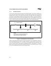
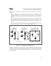
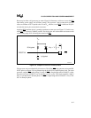
To examine the parallel resonant frequency, refer to Figure 5-3(c), an equivalent circuit to Figure
5-3(b). The capacitance connected to L
1
is 200 pF in parallel with 20 pF. The equivalent capaci-
tance is still about 200 pF (within 10%) and the equation in Figure 5-4(a) now yields the parallel
resonant frequency.
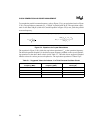
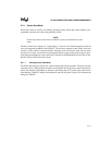
Figure 5-4. Equations for Crystal Calculations
The equation in Figure 5-4(b) yields the equivalent capacitance C
eq
at the operation frequency.
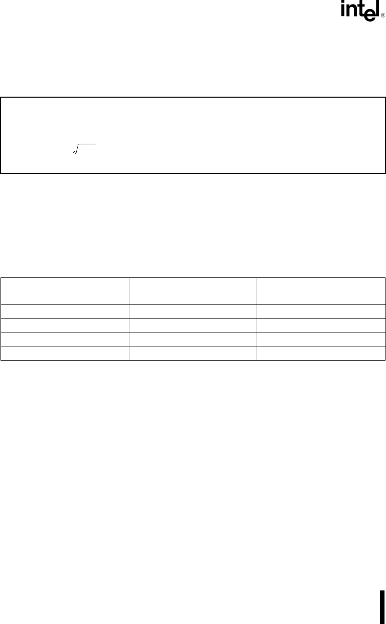
The desired operation frequency is the third overtone frequency marked on the crystal. Optimiz-
ing equations for the above three criteria yields Table 5-1. This table shows suggested standard
inductor values for various processor frequencies. The equivalent capacitance is about 15 pF.
Table 5-1. Suggested Values for Inductor L
1
in Third Overtone Oscillator Circuit
CLKOUT
Frequency (MHz)
Third-Overtone Crystal
Frequency (MHz)
Inductor L
1
Values (µH)
10 20 10.0, 12.0, 15.0
12 25 6.8, 8.2, 10.0
16 32 3.9, 4.7, 5.6
20 40 2.2, 2.7, 3.3
(a) Series or Parallel Resonant Frequency (b) Equivalent Capacitance
f
1
2π L
1
C
1
-------------------------= C
eq
ω
2
C
1
C
x2
L
1
C
1
– C
x2
–
ω
2
C
1
L
1
1–
-----------------------------------------------------------=