


201Setup
Chapter 1 MVS-8000 Functions
• Video Proc Memory: Enable or disable video process memory.
• Show Key: Enable or disable show key for edit preview, M/E and P/P Pvw/
K-Pvw.
• Key Auto Drop: For each switcher bank (M/E-1 to M/E-3, PGM/PST),
specify a key to be turned off automatically when you press a cross-point
button for the bus to be output as the background.
• Mask/Border Process: Set the processing order of masks and borders for
each M/E or P/P bank.
• Key Priority: Set the key priority operation mode for each of the M/E and
P/P banks. In DSK mode, the key priority is fixed.
• Xpt Hold mode: Set the operation mode for the cross-point hold button
provided on the key bus for each of the M/E and P/P banks.
• Pattern Limit Transition: Set the operation mode when the pattern limit is
released for each of the M/E and P/P banks.
• Wipe Edge Default: Adjust the wipe edge softness for each of the M/E and
P/P banks.
• CCR Internal Signal Enable: Select whether signals generated internally to
the switcher can be select as input material to the color corrector. (MVS-
8000G/8000GSF only)
• FM Auto Store: Switch on or off the function to automatically attach a name
and save in frame memory.
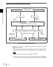
Link settings (Link)
• Internal Bus Link: Make a setting of the bus link function that links
together two buses internal to the switcher.
• GPI Link: Make settings for linking any cross-point buttons or [CUT] and
[AUTO TRANS] buttons in the cross-point control block and GPI output
ports.
• M/E Link: Make settings to link together two M/E banks.
• Key Trans Link: Make settings to link key transitions.
External device connections (Device Interface)
• Remote Assign: Set the use of the four 9-pin ports.
• GPI Input: Set the GPI input ports and trigger polarities, and make the
action settings.
• GPI Output: Set the GPI output ports and trigger polarities, and make the
action settings.
• Aux Control: Set whether operations on the AUX buses from the four 9-pin
ports are inhibited.
• DME Type Setting: When the DME is an MVE-9000 or MVE-8000A, carry
out interface settings, and for an SDI interface set the AUX bus outputs and
reentry inputs.