


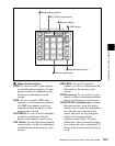
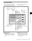
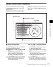

269Names and Functions of Parts of the Control Panel
Chapter 2 Menus and Control Panel
selected, this button lights
automatically.
BDR (border): Apply a border of a
uniform thickness to the whole key.
DROP BDR (drop border): Apply a
border to two sides of the key (for
example, below and to the right, or
below and to the left).
SHDW (shadow): Apply a shadow to two
sides of the key (for example, below
and to the right, or below and to the
left).
OUTLINE: Use the outline of the key.
EMBOS (emboss): Apply an embossing
effect to the periphery of the key.
• To select a “normal” as the edge type
(that is, a plain edge), set all five of the
above buttons off.
• When border, drop border, or shadow is
selected, you can use a special color
matte or a signal selected on the utility 1
bus for the edge.
• When emboss is selected, you can use the
dedicated color matte signal for the
emboss function.
• When outline is selected, the signal
selected on the key fill bus is used to fill
the edge.
MAIN MASK: Press this button, turning it
on, to enable the key mask using the
main pattern. It also enables you to set
the parameters with the knobs.
SUB MASK: Press this button, turning it
on, to enable the key mask using the
sub pattern. It also enables you to set
the parameters with the knobs.
ZABTN (zabton): When this is pressed,
turning it on, a translucent pattern is
inserted behind the key. With the
knobs, you can adjust the color, size,
density, and softness parameters.
SOFT EDGE: Soften the edge of the key.
e MORE button
When there are more than four parameters,
this button lights amber. When it is pressed,
it changes from amber to green and the fifth
and subsequent parameters are assigned to
the knobs, allowing them to be adjusted.
f SHOW KEY button
While this button is held down, a key
processed key source signal is output from
the specified output port. You can make the
output specification independently for each
of edit preview and the preview of each M/
E or PGM/PST bank in a Setup menu.
g Knobs
Turn the knobs to adjust the parameter
values.
h Displays
Each display shows the initial letters of the
parameter name and the parameter value
(maximum three digits including a minus
sign for a negative value).
i DME channel selection buttons
Press one of these buttons, turning it on, to
delegate a DME channel to the keyer. The
number of valid DME channel selection
buttons depends on the number of channels
installed in the DME processor.
A maximum of four consecutively
numbered DME channels from the two sets,
DME 1 to 4 and DME 5 to 8, can be
assigned to one keyer. A DME channel
assigned to a keyer cannot be selected on
another keyer. However, using the override
function it is possible to allocate a channel
already allocated to another keyer to the
currently selected keyer. If DME channel
allocations have been made in a Setup
menu, these buttons cannot be used to make
DME channel allocations. Using the trace
function, it is possible to check which keyer
a DME channel is allocated to.