


229Simple P/P Software
Chapter 1 MVS-8000 Functions
a) In DSK mode, the backgrounds that can be selected in the PGM Config menu are restricted to
background 1 and background 2.
b) Depends on the setting in the Engineering Setup >Switcher >Config >M/E Output Assign menu.
OUT5 and OUT6 cannot be used.
Connectors for which a P/P row output signal can be selected
For an edit preview bus or AUX bus assigned to output connector OUT23 or
OUT24, you can select a P/P row output signal.
If these buses are assigned to other than OUT23 or OUT24, then it is not
possible to select a P/P row output signal. (Assigning these buses to the two
connectors is recommended.)
Format converter output restrictions
On the MVS-8000G, the signal output from the format converter output
connectors (FC1, FC2) can be assigned in either of the following ways.
• Out#15-16: Assignment fixed, signals OUT15 (for FC1), and OUT16 (for
FC2).
• Out#17-22: Select from the OUT17 to OUT22 signals. (It is not, however,
possible to select the same signal for FC1 and FC2.)
It is not possible to select FC1 and FC2 differently. For example, it is not
possible to select “Out#15-16” for FC1 and “Out#17-22” for FC2.
FC3 and FC4 always have the same signals assigned: OUT39 and OUT40
respectively, and therefore it is not possible to select OUT17-OUT22.
Logical assignment of the physical PGM/PST
In the Engineering Setup >Switcher >Config >Logical M/E Assign menu, it is
not possible to assign the physical PGM/PST as a logical PGM/PST.
In the <Logical M/E to Physical P/P> group, you can select from M/E-1, M/E-
2, and M/E-3.
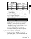
Output
connector
Fixed assigned outputs
Standard mode Multi-program mode
DSK mode
a)
OUT17 Program
P/P OUT1
b)
Program 1
OUT18 Program
P/P OUT1
b)
Program 2
OUT19 Preview
P/P OUT2
b)
Key preview 1
OUT20 Clean
P/P OUT3
b)
Key preview 2
OUT21 Key preview
P/P OUT4
b)
Clean 1
OUT22 Preset Preset Clean 2
Output connector Assignable bus
OUT23 Edit preview bus
OUT24 AUX bus