


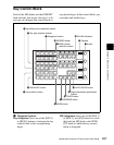
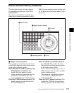
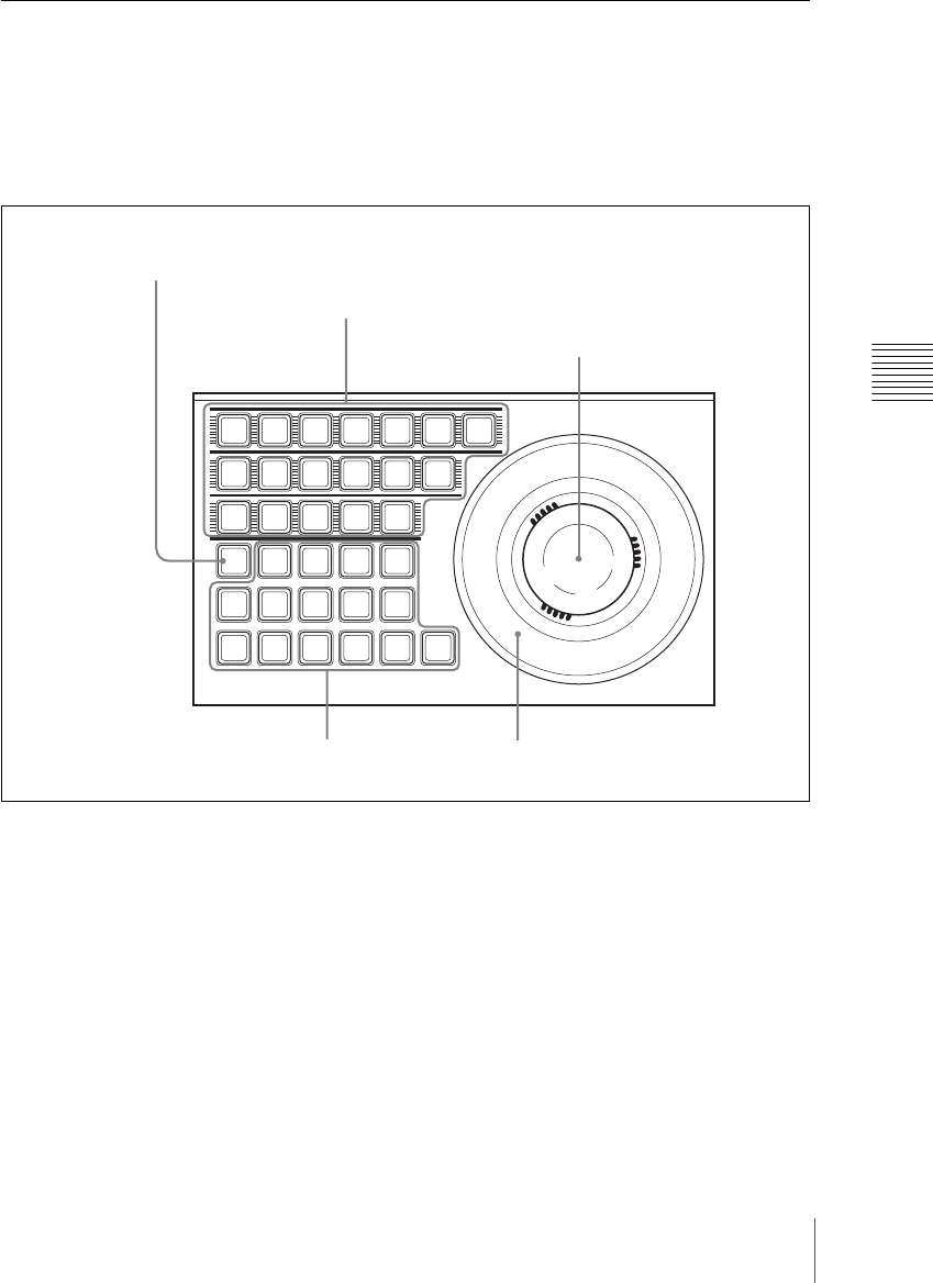
271Names and Functions of Parts of the Control Panel
Chapter 2 Menus and Control Panel
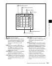
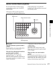
Device Control Block (Trackball)
The description below of frame memory
clip operations applies only to the MVS-
8000A/8000G.
The device control block is used for three-
dimensional transform operations using a
DME, for wipe pattern position setting, and
for VTR/disk recorder/frame memory clip
operation.
a Region selection buttons
The operation mode allocated to the device
control block depends on the selection state
of the region selection buttons.
When the [M/E 1], [M/E 2], [M/E 3], and
[P/P] buttons are selected: This
enables the wipe pattern position
setting (positioner) operation mode in
the device control block. You can
select multiple buttons simultaneously.
When the [USER] button is selected: This
enables pattern position setting used
for color backgrounds.
When the [DME 1] to [DME 8] buttons
are selected: This enables the three-
dimensional transform operation mode
in the device control block.
Press a button, turning it on, to select a
DME channel. You can select multiple
buttons simultaneously.
The number of valid buttons depends
on the number of DME processor
channels installed.
When the [DEV] button is selected: This
enables the VTR/disk recorder/frame
memory operation mode in the device
DEVUSER
M/E1
DME1
DME5
MENU
SHIFT
M/E2
DME2
DME6
ASP
PERS
SUB
LOC
SIZE
ASP
AXIS
LOC
MAIN
LOCAL
K1
CB1
GLB
K2
CB2
CLR
WORK
BUFR
M/E3
DME3
DME7
LOC
XYZ
LOC
ROT
POS
RSZR
X
P/P
DME4
DME8
Y Z CTR
RUN
CTRL
SRC
K3
TRGT
K4
RSZR
CTRL
1 Region selection buttons
3 Trackball
4 Z-ring
2 Operating buttons
5 MENU button