


87Frame Memory
Chapter 1 MVS-8000 Functions
About extended clips
When two frame memory boards (MKS-8440A for the MVS-8000A, MKS-
8442G for the MVS-8000G) are installed, one is dedicated to clips. Such clips
held in a frame memory board are called “extended clips.”
Use of frame memory
There are eight frame memory channels, FM1 to FM8, and each channel
independently allows a freeze image to be saved or recalled.
By allocating FM1 to FM8 to cross-point buttons you can use the still image
output or clip output from each channel as input material.
Note
On the MVS-8000A, an extended clip can only be recalled from FM1 or FM2.
It is not possible to recall from FM3 to FM8. Note that this restriction does not
apply to the MVS-8000G.
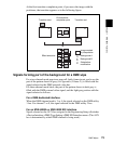
Correspondence between input and output
There are two buses for capturing frame memory material: the frame memory
source 1 bus and the frame memory source 2 bus.
These input buses are used by allocation to one of the pairs of output, FM1&2,
FM3&4, FM5&6, and FM7&8. You can freeze a frame in each channel
separately, or freeze in the two channels simultaneously.
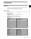
The source buses allocated to FM1 to FM8 are as follows.
Pair mode
By enabling the pair mode, you can link FM1 and FM2, FM3 and FM4, FM5
and FM6, and FM7 and FM8. For example, when a freeze or image processing
is carried out on FM1, the same operation is carried out on FM2. The same
applies to the other pairs. When a pair of images are captured in pair mode, the
image frozen in FM1 (3, 5, or 7) is referred to as the main file and the other
frozen in FM2 (4, 6, or 8) is referred to as the sub file.
Input Frame memory source bus 1 Frame memory source bus 2
Output FM1 FM2
FM3 FM4
FM5 FM6
FM7 FM8