


79DME Wipes
Chapter 1 MVS-8000 Functions
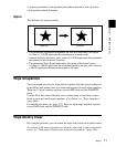
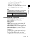
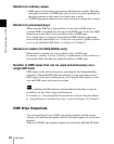
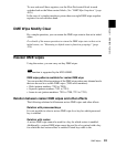
At the first transition completion point, if you move the image with the
positioner, the transition appears as in the following figure.
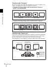
Signals forming part of the background for a DME wipe
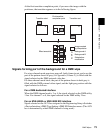
For a two-channel mode page turn, page roll, brick, frame in-out, and so on, the
part of the pattern shown in gray (see Appendix (Volume 2)) is filled with the
signal selected on the DME external video bus.
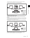
For three-channel mode brick, the part of the pattern shown in dark gray is
filled with the DME external video signal, and the light gray portion with the
signal selected as follows.
For a DME dedicated interface
When the DME channel used is 3 or 4, the signal selected on the DME utility
1 bus. For channel 7 or 8, the signal selected on the DME utility 2 bus.
For an MVE-8000A or MVE-9000 SDI interface
Signal selected on the AUX bus assigned in the Engineering Setup >Switcher
>Device Interface >DME Type Setting >DME SDI interface menu. (The AUX
bus is determined by which DME channel is being used.)
State before
modification
Image created
by interpolation
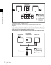
Background B
Background A
Transition start Transition end
First transition
completion point
Effect execution