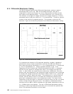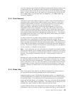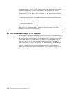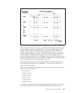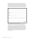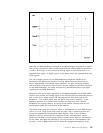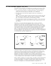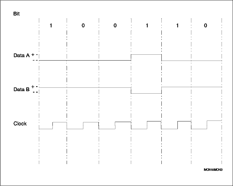
Figure 83. 8260 Backplane Signalling for 16 Mbps Operation
Note that the 8260 backplane interface is completely
digital
, whereas the signals
sent on the transmission media (lobe cables and the cabling between two hubs)
is said to be
analog
. In this context an analog signal is one where there is no
separate clock signal. A digital signal is one where there are separate data and
clock signals.
The use of digital signals on the 8260 backplane allows the signals to be
switched to the appropriate location by using digital switches which can be
easily implemented on the 8260 media modules. Per-port switching modules,
where different ports on the same module may be assigned to different networks
on the 8260 backplane, are made economically possible because of the digital
signalling on the 8260 backplane.
Because of the use of digital signalling on the 8260 backplane, each 8260 media
module must convert the analog signal it has received from the attached stations
and convert it to a digital signal and then present the data and clock to the
backplane. This is done within both the active and passive modules. In the
opposite direction, the modules must receive the data and clock from the
backplane and convert them to an analog signal before sending them on the
transmission media for transmission to the stations.
The Phase Lock Loop (PLL) function which is implemented on each 8260 module,
(DPLL is in 8.3, “Dual Phase Lock Loop” on page 138) is used to perform the
conversion between the analog and digital signals. Also, in the 16 Mbps
operation, the PLL will double the frequency of the received digital signals
(clocked at 16 MHz) to form analog signals (clocked at 32 MHz) for transmission
on the lobes, and does the opposite for the signals sent to the backplane from
the lobe. In the 4 Mbps mode, the PLL does not change the frequency of the
Chapter 8. 8260 Token-Ring Support 137


