applicable to the LAN ports and will not be discussed any further in this
book.
11.8.2.1 Configuring Physical Port Parameters
The
Physical Port List
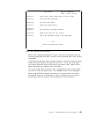
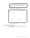
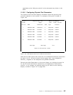
panel displays information about the physical ports
currently installed on your module. An example of this panel is shown in
Figure 146.
Config * Physical Port List Module: BladeRunner
System Page 1 Time: 15:39 5 Jan 95
Port ID Name Connection Card Type Protocol
1 PHYSICAL PORT Ethernet-1 0 Backplane csmaLan
2 PHYSICAL PORT Isolated 0 Backplane csmaLan
3 PHYSICAL PORT Isolated 0 Backplane csmaLan
4 PHYSICAL PORT Isolated 3 Backplane csmaLan
5 PHYSICAL PORT Isolated 3 Backplane csmaLan
6 PHYSICAL PORT Isolated 3 Backplane csmaLan
Prev Page Next Page Exit
Return to the previous screen
Figure 146. LMS Physical Port List for Ethernet Connections
Note that the above panel also shows the list of backplane Ethernet connections
for ports 1 thru 6. As can be seen from this panel, port 1 was assigned to
Ethernet_1 segment on the backplane using DMM commands.
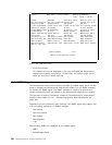
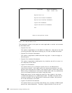
Selecting the
Next Page
option on this panel allows you to display the port list
for any I/O cards that may be installed on your Multiprotocol Interconnect
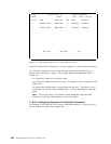
module. In our example, we had two token-ring I/O cards, so the resulting
display is shown in Figure 147 on page 258.
Chapter 11. 8260 Multiprotocol Interconnect Module 257


