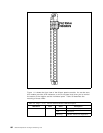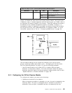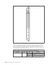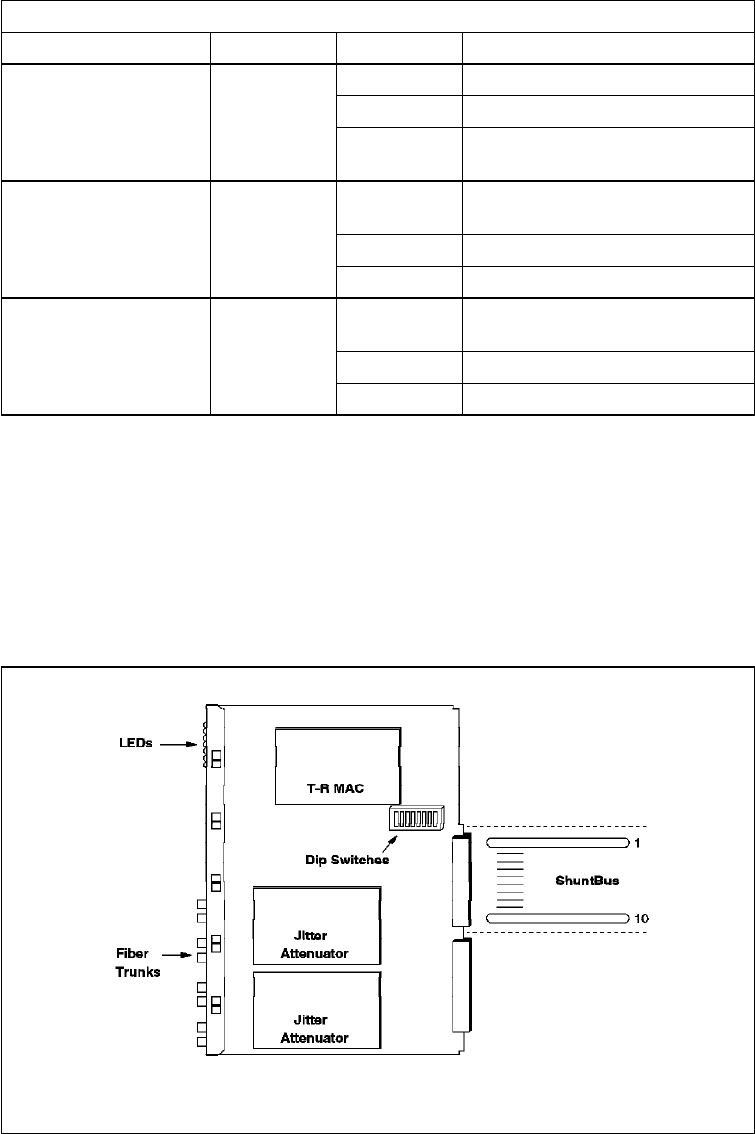
Figure 114 shows the side view of the dual fiber repeater module. As can be
seen, in addition to the 11 isolated segments and the mounting for one T-MAC,
there is an 8-position DIP switch located on the module. These DIP switches are
used in the absence of an installed management module in the 8260. However,
if a management module is installed in your 8260, the setting of these DIP
switches will be ignored unless ″DIP_CONFIGURATION″ is enabled for DMM. For
more information, please refer to 4.2.4.4, “ Configuring DMM Device” on
page 50.
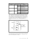
Table 31 (Page 2 of 2). Dual Fiber Repeater Module LED Descriptions
LED Name Color State Description
RI/RO Green On Trunk enabled and operating
Off Trunk disabled.
Blinking Trunk enabled but not
operating normally
JA1 and JA2 Green On JADC card installed and
operating normally
Off JADC card not installed
Blinking JADC card failed diagnostics
Port Status Green On Port enabled and operating
normally on the ring
Off Port disabled
1 blink Port enabled, no phantom
Figure 114. Dual Fiber Repeater Module Side View
The DIP switch settings on this module are identical to those of the 18-port active
per-port switching module which is described in 9.3.1, “Configuring the 18-Port
Active Per-Port Switching Module” on page 177.
Chapter 9. 8260 Token-Ring Modules 187


