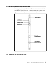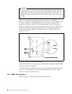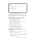
The lower port is the
auxiliary
port and can be jumpered for RS-232 or RS-423
operation. This port allows you to attach a terminal locally (or via modem) to
DMM. Note: The default is RS-232. See Table 7 on page 42 for the pinout of the
cables used for attaching terminals to the auxiliary port.
Note
You can attach terminals to both the console and auxiliary port at the same
time, and both of them will be able to access the DMM simultaneously.
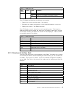
Table 7. Auxiliary Port Pinouts
Pin # Signal Name
1 Carrier detect (CD)
2 Receive data plus (RX+)
3 Transmit Data (TX)
4 Data terminal ready (DTR)
5 Signal ground (SG)
6 Data set ready (DSR)
7 Request to send (RTS)
8 Clear to send (CTS)
9 Receive Data Minus (RX-) if RS-423, otherwise no connection
4.2.3.1 Modems for Connecting Terminals to DMM
The console port and auxiliary port can be used to connect a modem for remote
dial-in. The following requirements must be met:
1. The modem must be 100% Hayes compatible.
2. Any of the following baud rates may be used:
300, 1200, 2400, 9600, 19,200 or 38,400
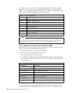
3. The modem must be placed in Dumb/Auto Answer mode. This can be done
by entering the commands listed in Table 8 from a terminal directly attached
to the modem.
** If you issue the
Set Terminal Hangup Enable
command for modem use, you
must change the DTR parameter as defined by the ″at&d2″ command to ensure
Table 8. Commands Required to Set Up the Modem for the Console Port
Commands # Definition
at&f [enter] Restore factory defaults
at&d0 [enter] Ignore changes in DTR status **
ats0=1 [enter] Auto-answer on first ring
ats0? [enter] Verify Auto-answer (should return 001
atq1 [enter] Does not return result codes
at&W [enter] Save this configuration
at&Y [enter] Define this configuration as the default
at&d2 [enter] Indicates hangup and assumes command state when
an On to Off transition of DTR occurs **
42 8260 Multiprotocol Intelligent Switching Hub


