


Caution
As always, great care should be taken when handling logic cards. The level
of static electricity that can build up in the human body can be thousands of
times greater than the very small switching voltage used in logic cards. An
analogy would be connecting your Hi-Fi or TV set to 10,000 volts. It wouldn′t
last long!
Remove the card from its shipping container and check it for damage.
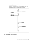
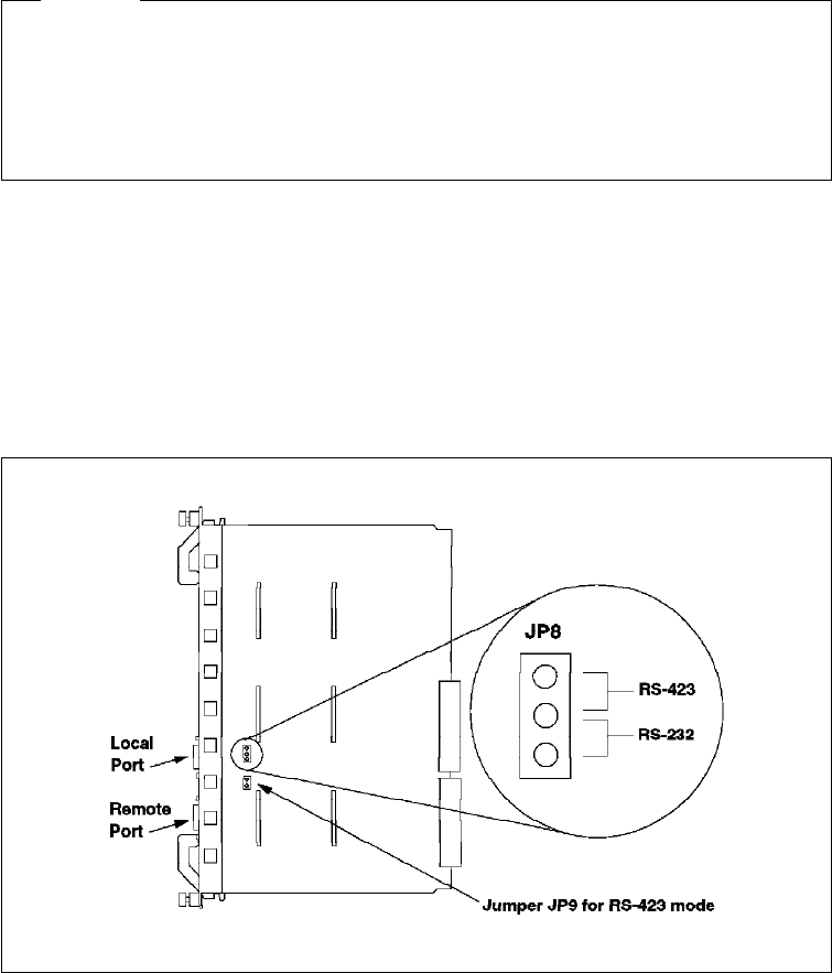
There are 2 jumper blocks that may need to be changed. Namely, JP8 and JP9
as shown in Figure 16. These jumpers allow you to set the auxiliary DB-9
connector to RS-232 or RS-423. For the factory default, which is RS-232, the
jumper will be between pins 2 and 3 (the bottom 2 pins) of JP8. To select RS-423
mode, the jumper on JP8 should be changed to pins 1 and 2 (the upper pins).
For RS-423, the jumper MUST be installed on JP9. For RS-232, remove the
jumper from JP9.
Figure 16. Jumpering for the DMM DB-9 Ports
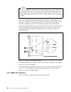
Holding the DMM by the faceplate, slide it into the slot in the 8260. Like all 8260
modules it can be hot plugged.
If the DMM has been installed correctly and is functioning the status LED should
come on. The LCD display should show
diag
then either
rdy
for the master
module or
stby
for a backup module.
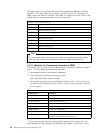
4.2.2 DMM LED Indicators
Table 4 on page 41 shows the meaning of the status LED.
40 8260 Multiprotocol Intelligent Switching Hub