3.1.1 The Controller Module Front Panel
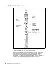
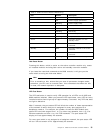
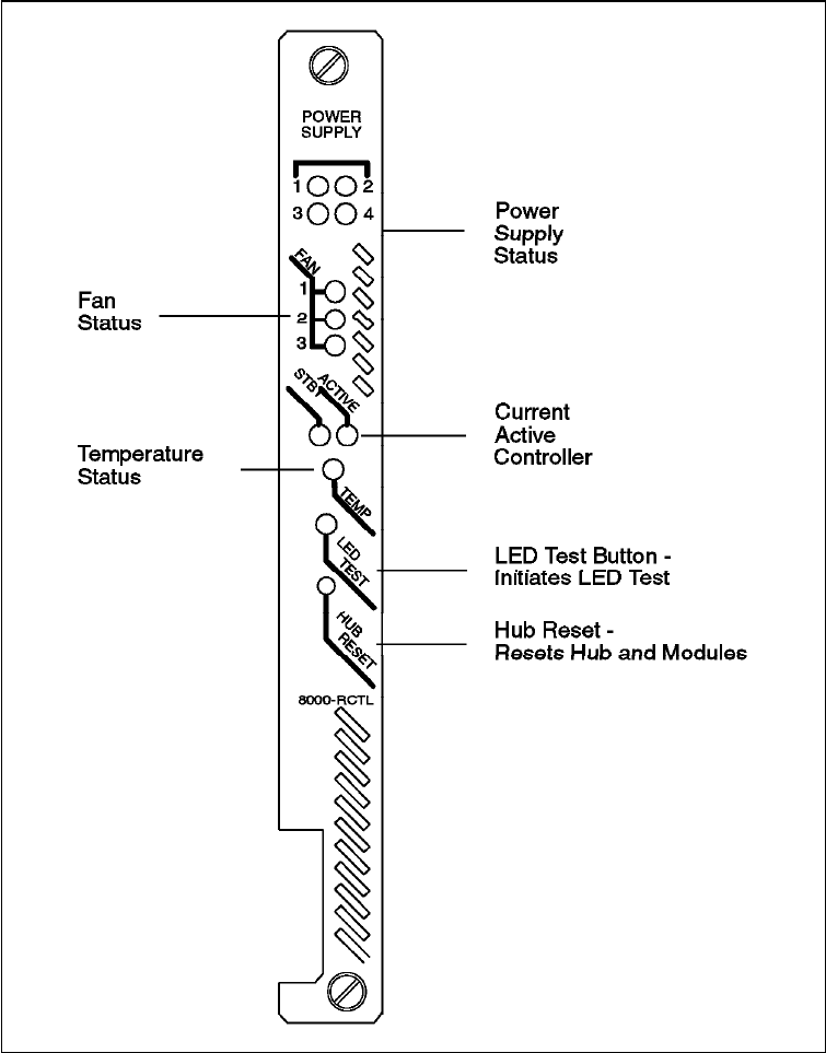
Figure 13. Front View of the Controller Module
Figure 13 shows the front view of the controller module.
Besides the hub reset and the LED test buttons, the controller module has 10
LEDs covering the 4 power supplies, 3 fans, active or standby mode and
temperature on the front panel which indicate the state of the system
environment. The names and locations of the buttons and LEDs are shown in
Figure 13. The following table describes the meaning of the LEDs:
30 8260 Multiprotocol Intelligent Switching Hub


