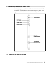
3.1.4 8260 Fault Tolerant Controller Module Considerations
•
Up to two controller modules can be installed in the 8260 hub.
•
Neither controller module occupies a payload slot.
•
When 2 modules are installed, one is active and the other is standby.
•
The hub reset button is only active on the active controller module.
•
The LED test button is active on both active and standby controller modules.
•
When a DMM is the active management module, the controller module will
be seen in either slot 18 and/or 19.
•
When an 8250 xMM is the active management module, the controller module
will be seen in slot 17 although it physically resides in slot 18 and/or 19. As
a result, when an 8250 management module is to be the master
management module in the 8260, slot 17 must be empty or have the 8250
Right Boundary Adapter installed.
•
When an 8250 xMM is the active management module, the standby controller
module is invisible to the xMM. However, as soon as the standby controller
module becomes the active controller module, it is then automatically seen
by xMM to be in slot 17.
•
When there is no DMM installed on the 8260 and an 8250 xMM is used as the
master management module, one of the following levels of the xMM is
required to identify the active controller module in slot 17:
− EMM version 4.0 (or later)
− TRMM version 2.1 (or later)
− FMM version 2.0 (or later)
•
The 8250 controller module can not be used in the 8260 hub.
•
The 8260 controller module can not be used in the 8250 hub.
•
One active controller module is always required to operate the 8260 hub.
•
It is recommended to have a second controller module installed for
redundancy.
•
The switch over from the active controller module to the standby controller
module is disruptive to the operation of the network.
Chapter 3. 8260 Fault Tolerant Controller Module 33


