


This pin is used to provide a means of detecting collisions of the segments
using method 3. Analog collision detection is described in 2.2.2, “Analog
Collision Detection” on page 19.
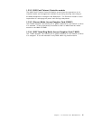
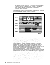
2.2.1 Digital Collision Detection
Collision detection on the backplane (for methods 1 and 2) is done by using
slot-id information transmitted on the backplane. Each module asserts its own
slot-id one bit time before transmitting user data on the data pin. The following
bit time, the module reads the slot-id received on these pins and compares it
with its own slot-id. If only one module is transmitting, the transmitted and
received slot-id values are the same and no collision exists. If more than one
module is transmitting, then at least one module will detect an unequal slot-id
comparison and will then signal local collision.
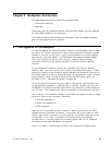
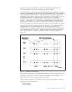
It should be noted that slot-id mismatches will not always occur in all modules
involved in a collision. This is because, the slot-id sent on the bus is the ′OR′ of
the two or more slot-ids transmitted by the individual modules. For example, if
the module in slot 8 (B′0111′) collides with the module in slot 1 (B′0000′), the
backplane will ″OR″ the two together and both modules will see B′0111′. This
will look all right to the module in slot 8, so it will not assert the local collision
pin. However, the module in slot 1 will detect the slot-id mismatch and will
assert the local collision pin.
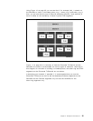
2.2.2 Analog Collision Detection
To perform analog collision detection, a current source is used to generate a
level on the backplane. Each time a module starts transmitting, the voltage on
the backplane drops. If more than one module is transmitting at the same time,
the drop at the voltage level is used to detect such a condition.
2.2.3 Statistics Collection
The slot-id in conjunction with the port-id and the user data is used by the
Management module to collect statistical information about the ethernet_1,
ethernet_2 or ethernet_3 segment as well as the individual ports and modules on
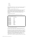
that segment. For method 1 the slot-id and port-id are sent by the module in
parallel over 9 pins on the backplane, whereas, modules employing methods 2
and 3 use a single pin on the backplane to transmit their slot-id and port-id.
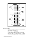
2.3 Token-Ring Segments on the Backplane
The 8260 allows you to set up a maximum of 7 token-ring segments on the
Enhanced TriChannel using the 8250 modules. Also, you can set up 10
token-ring segments on the ShuntBus using the 8260 token-ring modules. Note
that the 8250 token-ring modules only connect to the Enhanced TriChannel and
the 8260 modules only connect to the ShuntBus; therefore, if you want to set up a
token-ring segment consisting of these two different types of modules, you must
connect the segments together using RI/RO connections, bridges, or routers.
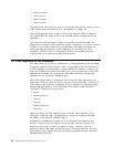
Each 8250 token-ring module which is assigned to one of the 7 token-ring
networks on the Enhanced TriChannel uses one of the resources called a
token-ring path
. There are 15 token-ring paths on the Enhanced TriChannel and
they are referred to as tr_path_8250_1 through tr_path_8250_15. Each token-ring
path utilizes 4 pins on the Enhanced TriChannel. These pins are as follows:
Chapter 2. Backplane Architecture 19