


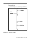
The LCD display and display control button are used to:
•
Display the current operating state of the module
•
Determine the network assignment of ports and 8260 modules in the hub
•
Display the version of the DMM microcode
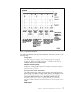
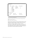
The LCD display normally shows the module operating state. To display the
DMM microcode version, press the button until the display reads
Vers
, and one
second after releasing the button the version will be displayed. Table 5 shows
the possible states of the display.
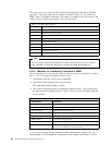
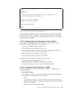
Table 4. DMM Status LED
LED
name
Color State Indicates
Status Green OFF Power off or module failure
ON Power on and software functioning properly
Blinking Power on but diagnostics have failed
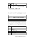
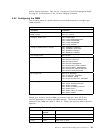
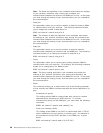
Table 5. DMM LCD Display
Display Definition
Diag The DMM is running diagnostics
Rdy The DMM is the active (master) management module
Stby The DMM is in standby mode
Dnld New microcode is being downloaded
Vers Microcode level of the DMM
LED Displays when the controller LED test button is pressed
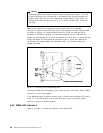
4.2.3 Console and Auxiliary Ports
There are two DB-9 ports on the faceplate of the DMM. The upper port is called
the
console
port and is used for attaching a terminal locally (or via a modem) to
the DMM. This terminal is used to provide out-of-band management capability
for the 8260. See Table 6 for pinout of the cable used for attaching terminals to
this port.
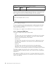
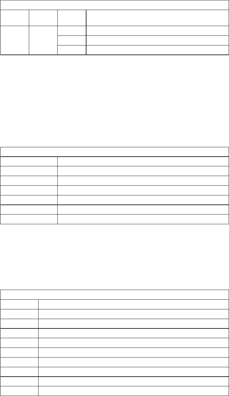
Table 6. Console Port Pinouts
Pin # Signal Name
1 Carrier detect (CD)
2 Receive data (RX)
3 Transmit Data (TX)
4 Data terminal ready (DTR)
5 Signal ground (SG)
6 Data set ready (DSR)
7 Request to send (RTS)
8 Clear to send (CTS)
9 No connection
Chapter 4. 8260 Distributed Management Architecture 41