


Service functions 50 through 99 are enabled when you select Manual mode and
enter function 25 (service switch 1), then function 26 (service switch 2).
Subfunctions are used with Functions 51 and 54 through 64.
You can disable the service functions by selecting and entering either function 25
(service switch 1) or function 26 (service switch 2).
Using Subfunctions: After you select and enter the function (51, or 54 through 64),
the subfunction field appears with two asterisks (**). You can now select and enter
a subfunction value. When you have selected and entered a value, actual data, YY
FF (where YY is the function number), is displayed. The ’YY FF’ response indicates
that no data is present for this subfunction value. The data displays as 8
hexadecimal digits (4 bytes of data).
You can repeat these steps for different subfunction values. To exit subfunctions,
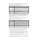
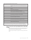
select and enter the two asterisks for the subfunction value. Table 25 shows an
example of a subfunction data display.
Table 25. Subfunction Data Display Example
Function Subfunction Data Display
51 ** Subfunction mode entered
51 00, 01 NIA (8 bytes)
51 02, 03 Current TDE (8 bytes)
Function 50–System Processor Stop: This function stops the system processor.
Attention: This function might cause the system to end abnormally. Use only when
directed by your next level of support.
Function 51–System Processor Status: This function displays the following
values:
v Next instruction address (NIA)
v Current task dispatching element (TDE) address
The data can be displayed 8 digits at a time. Select and enter a subfunction
number to display each word of data from 00 to 0F.
Function 52–System Processor Start: This function starts the system processor
(after it has stopped).
Function 53–Path Switch: This function resets communication between the service
processor and the control panel.
Attention: Use this function only with proper supervision from your next level of
support.
Low-Level Debug (LLD) panel functions (Models 150, 170, 250,
4xx, 50x, 51x, 530, 53S, 6xx, 7xx, SB1, and Sxx)
You can enable these functions by selecting Manual mode, stopping the system,
and selecting Functions 25 and 26. Use these functions to analyze IPL errors. The
following is a list of all the low level debug (LLD) panel functions and a
description of each.
Function 54–Display I/O Configuration Table (ICT): The I/O configuration table
(ICT) contains the state of every I/O bus unit (IOBU) and bus extension unit that
Chapter 5. Control Panel Functions 171