


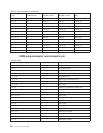
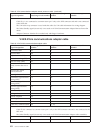
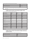
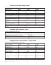
Table 63. EIA-232/X.21bis cable wrap connector wiring (continued)
Signal designation Wrap connector pin to pin
Data signal rate selector to carrier detector 23 to 8
DTE clock to RSET DCE, (TSET)
1
24 to 17, (15)
Select standby to TSET
1
11 to 15
Note:
1
Some cables do not contain the Select Standby to TSET wrap. In these cables, DTE Clock wraps to RSET
DCE and TSET.
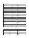
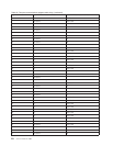
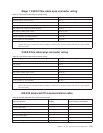
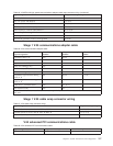
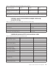
V.36/EIA 449 high speed communications adapter cable
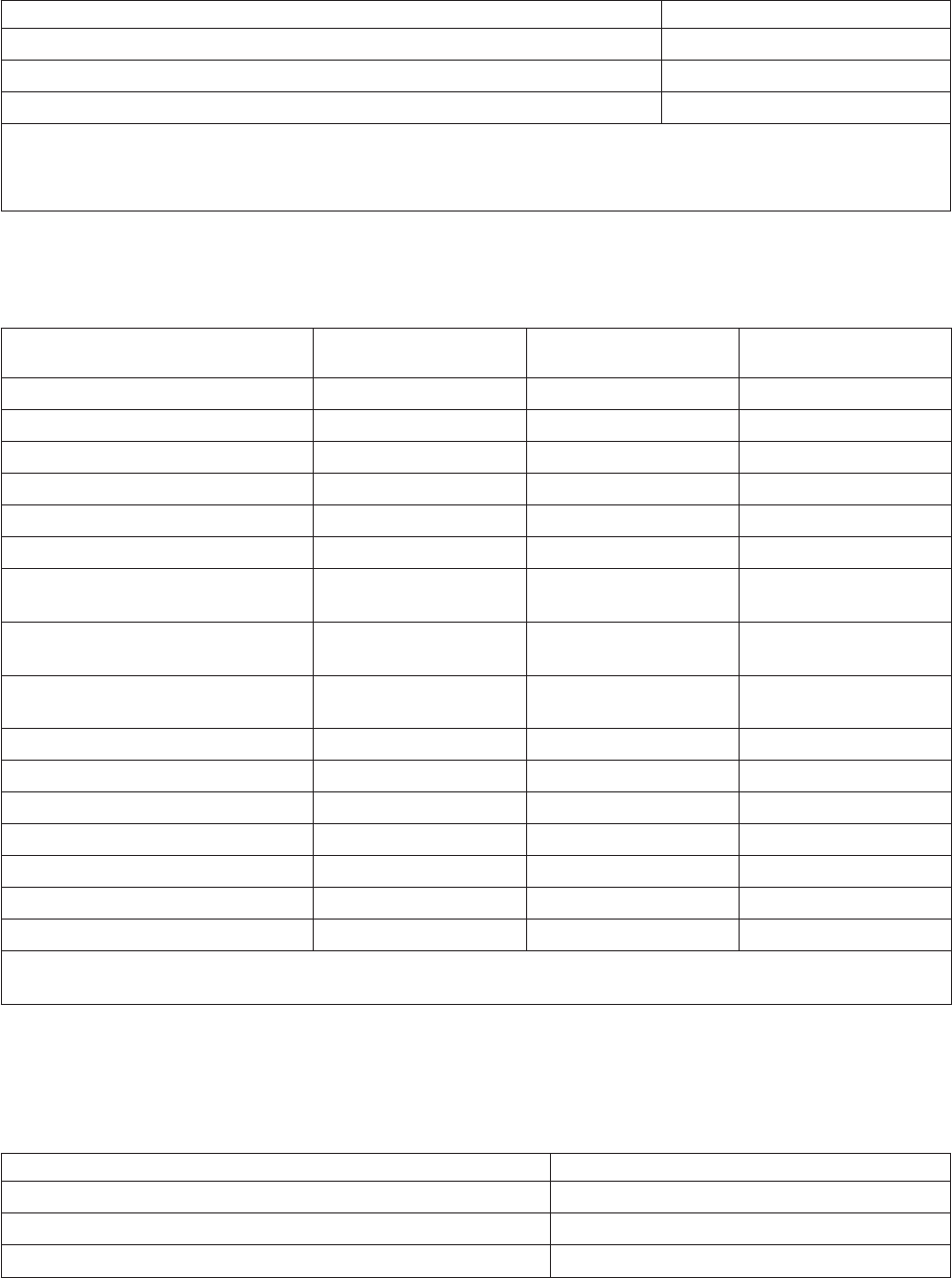
Table 64. V.36/EIA 449 high speed communications adapter cable
Signal designation
Interchange circuit
number
Adapter connector pin
number
DCE connector pin
number
Transmitted data A, B 103 18,34 4,22
Received data A, B 104 37,20 6,24
Request to send (RTS) A, B 105 4,21 7,25
Ready for sending (CTS) A, B 106 5,22 9,27
Data set ready (DSR) A, B 107 38,39 11,29
Data terminal ready (DTR) A, B 108 36,35 12,30
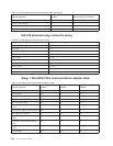
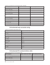
Received line signal (carrier) detector
(RLSD) A, B
109 8,25 13,31
Transmitter signal element timing
(DTE) A, B
113 10,27 17,35
Transmitter signal element timing
(DCE) A, B
114 40,41 5,23
Receiver signal element timing A, B 115 12,29 8,26
Calling indicator (CI) 125 11 15
Local loop back (LLB) 141 15 10
Remote loop back (RLB) 140 14 14
Test indicate (TI) 142 45 18
Receive circuit ground 28 20
Send circuit ground 47 37
Note: Cable ID 0, 2, 3 is connected to common return pin 7 only at the DTE connector end and is not connected at
the DCE end.
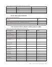
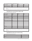
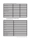
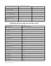
V.36/EIA 449 high speed communications adapter cable wrap
connector wiring
Table 65. V.36/EIA 449 high speed communications adapter cable wrap connector wiring
Signal designation Wrap connector pin to pin
Transmit data A to receive data A 4 to 6
Transmit data B to receive data B 22 to 24
DTR A to DSR A 12 to 11
256 Service Functions V5R2