


must run the test from a workstation that is not attached to the I/O adapter you
are testing. To run this test, you must have more than one workstation I/O adapter
on the system.
If this test completes successfully, the workstation I/O adapter card and the cable
that attaches to the workstation I/O adapter card are operating correctly.
If this test fails, a display indicates the probable failure rates of the workstation
I/O adapter card and the cable that attaches to the workstation I/O adapter card.
Communications tests
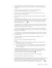
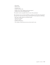
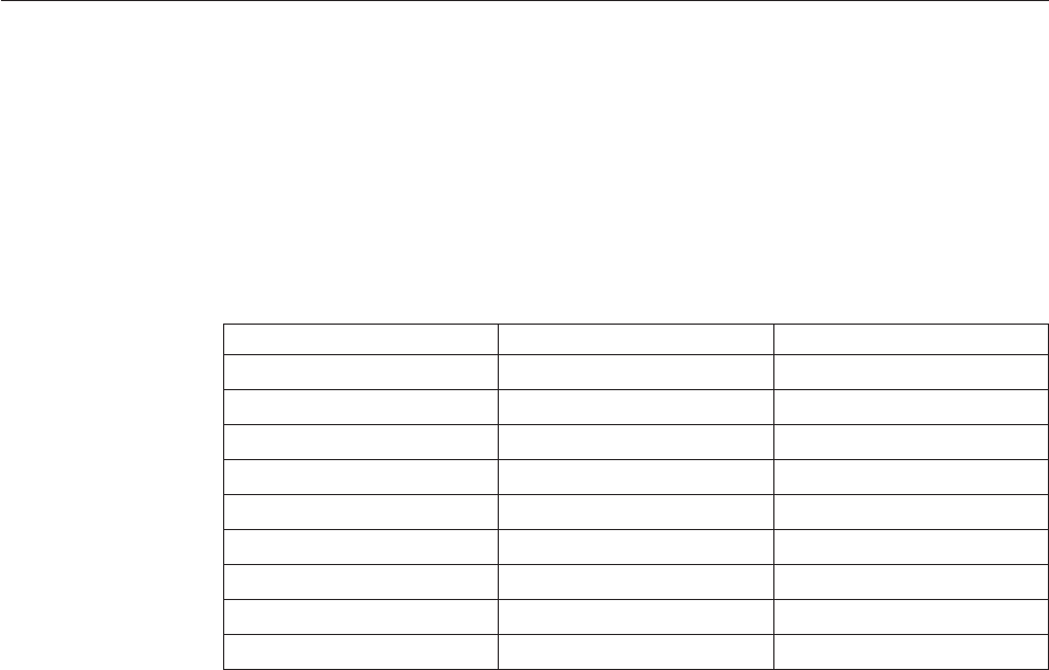
Wireless LAN adapter card indicators
The wireless local area network (LAN) adapter has two indicators located above
the 8-pin RS-485 connector.
The top-most indicator shows the adapter card status. The indicator closest to the
RS-485 connector shows data transmission or reception.
Use Figure 84 to assist in problem analysis.
Communications interface trace
The purpose of this test is to monitor the modem interface signals and to detect
wrong or incompatible use of the modem interface.
Starting the trace before varying on the communications lines provides the most
accurate sample of the lines that are coming up.
Test description
This test monitors the following five modem interface signals:
v Data Terminal Ready (DTR)
v Data Set Ready (DSR)
v Request To Send (RTS)
v Ready For Sending (CTS)
v Carrier Detect (CD)
Status Data Action
Blinking Green Off No action required
Solid Green Green (momentarily) No action required
Solid Red Solid Amber Run VFYCMN procedure
Solid Red Solid Red Run VFYCMN procedure
Solid Red Solid Green Run VFYCMN procedure
Off Off Run VFYCMN procedure
Solid Amber Solid Amber Verify configuration
Solid Red Off Verify configuration
Solid Amber Off Verify configuration
Figure 84. Wireless LAN adapter card indicators
316 Service Functions V5R2