


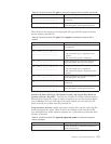
Table 33. SPCN functions in function 07 (continued)
AB Support-directed procedure only.
AC Support-directed procedure only.
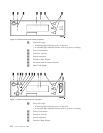
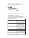
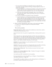
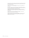
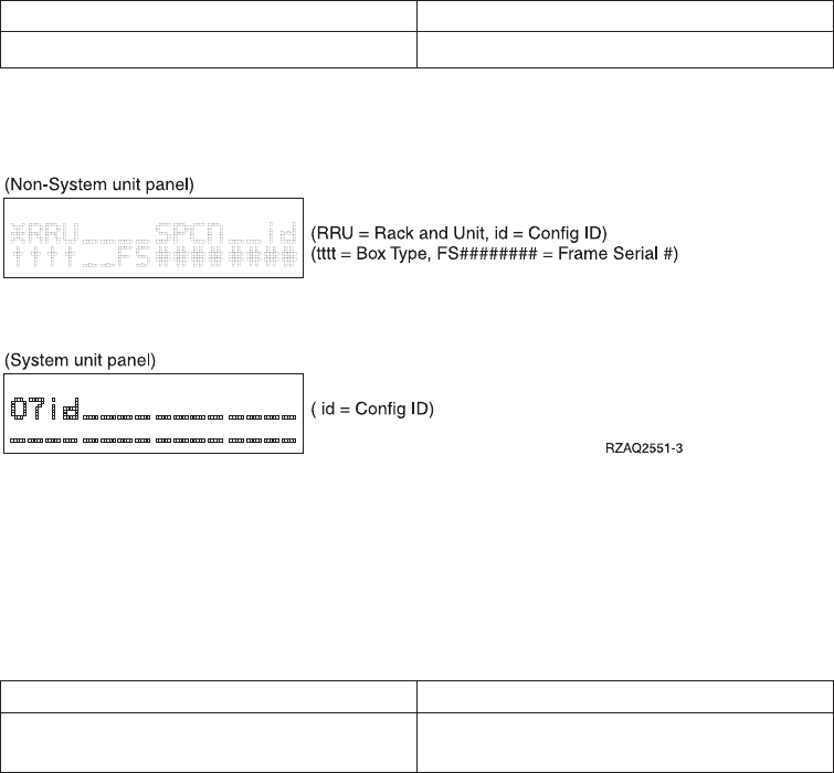
Figure 79 shows the diagram for function A6 or A8 on a Non-System unit panel
and function A8 on a System unit panel..
3. Use the Increment (↑) or Decrement (↓) buttons to select the frame on which to
perform the function that you selected in step 2 on page 182. Press Enter.
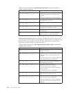
4. If you selected function A2, A3, A4, or A5 in step 2 on page 182, select the
appropriate fan or power supply listed in the following table to perform the
operation on.
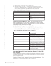
Fans Power supplies
00=B01, 01=B02, 02=B03, 03=B04 00=P01, 01=P02, 02=P03, 03=P04, 04=P05,
05=P06
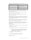
5. If you selected function A6 or A8 in step 2 on page 182:
v If a non-system unit address was selected in step 3, the non-system unit
display panel should be blinking and displaying data as shown in Figure 79.
v If a system unit address was selected in step 3, use the Increment (↑)or
Decrement (↓) buttons to scroll to 07xx, where xx is the configuration ID.
The configuration IDs are defined as follows:
71 - xSeries Server Tower
80 - FC 5065/5066
81 - FC 5074/5079/8079
82 - FC 9079
83 - Model 830/SB2
84 - FC 5078/0578
89 - FC 5088/0588
8A - FC 5094/5294
8B - FC 5095
90 - FC 5075
91 - Model 270 CCIN 22A2, 22A4, 22A5, 2422 without FC 7104
92 - Model 270 CCIN 24A0, 24A2 without FC 7104
93 - Model 820 iSeries
95 - Model 270 CCIN 22A2, 22A4, 22A5, 2422 with FC 7104
96 - Model 270 CCIN 24A0, 24A2 with FC 7104
99 - FC 9094
6. If you selected function A7 in step 2 on page 182, select either C1 to power ON
the frame or C2 to power OFF the frame.
7. If you selected function A9 in step 2 on page 182:
Figure 79. Operations diagram for functions A6 and A8
Chapter 5. Control Panel Functions 183