


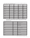
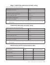
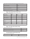

Stage 1 V.24/X.21bis cable wrap connector wiring
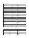
Table 57. V.24/X.21bis cable wrap connector wiring
Signal designation Wrap connector pin to pin
Transmit data to receive data A 2 to 3
RTStoCTS 4to5
DTR to DSR 20 to 6
Data signal rate selector to carrier detector 23 to 8
DTE clock to RSET DCE, (TSET)
1
24 to 17 (15)
Select standby to TSET
1
11 to 15
Remote loopback to calling indicator 21 to 22
Local loopback to test indicator 18 to 25
Note:
1
Some cables do not contain the Select Standby to TSET wrap. In these cables, DTE Clock wraps to RSET
DCE and TSET.
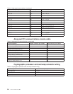
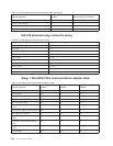
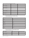
V.24/X.21bis cable wrap connector wiring
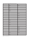
Table 58. V.24/X.21bis cable wrap connector wiring
Signal designation Wrap connector pin to pin
Transmit data to receive data A 2 to 3
RTStoCTS 4to5
DTR to DSR 20 to 6
Data signal rate selector to carrier detector 23 to 15 (17)
DTE clock to RSET DCE, (TSET) 24 to 25
Select standby to TSET
1
11 to 17
Remote loopback to calling indicator 21 to 22
Local loopback to test indicator 18 to 8
Note:
1
Some cables do not contain the Select Standby to TSET wrap. In these cables, DTE Clock wraps to RSET
DCE and TSET.
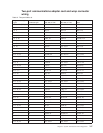
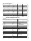
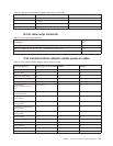
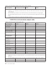
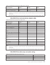
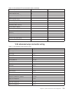
EIA 232 advanced PCI communications cable
Table 59. EIA 232 advanced PCI communications cable
Signal designation
Adapter connector pin
number DCE connector pin number
Transmitted data (TD) 13 2
Received data (RD) 6 3
Request to send (RTS) 2 4
Ready for sending (CTS) 33 5
Data set ready (DSR) 15 6
Signal Ground (SGND) 7,10,27 7
Received line signal (carrier) detector (CD) 20 8
Chapter 9. System Architecture and Configuration 253