


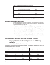
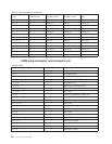
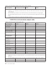
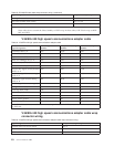

Table 55. V.24 communications adapter remote power-on cable (continued)
Signal designation Interchange circuit number
Adapter connector pin
number
DCE connector pin
number
Notes:
1
Cable ID 1, 2, 4 is connected to common return pin 7 only at the DTE connector end and is not connected
at the DCE end.
2
The V.24 cable wrap connector is used with this cable. See V.24 cable information for wiring diagram.
3
The Select Standby signal (circuit 116) is not used on all V.24 Communication Adapter Remote Power-On
cables.
4
Adapter Connector Number E1 is needed only with Stage 1 hardware.
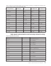
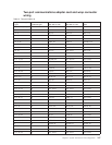
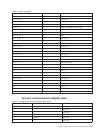
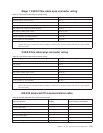
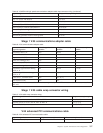
V.24/X.21bis communications adapter cable
Table 56. V.24/X.21bis communications adapter cable
Signal Designation
Interchange Circuit
Number
Adapter Connector Pin
Number
DCE Connector Pin
Number
Transmitted data 103 2 2
Received data 104 3 3
Request to send (RTS) 105 4 4
Ready for sending (CTS) 106 5 5
Data set ready (DSR) 107 6 6
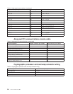
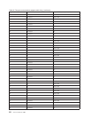
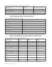
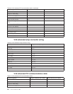
Data terminal
ready/connect data set to
line
108/2 20 20
Received line signal
(carrier) detector
109 8 8
Data signal rate selector 111 23 23
Transmitter signal element
timing (DTE)
113 24 24
Transmitter signal element
timing (DCE)
114 15 15
Receiver signal element
timing (DCE)
115 17 17
Select standby
2
116 11 11
Calling indicator 125 22 22
Remote loopback 140 21 21
Local loopback 141 18 18
Test indicator 142 25 25
Cable ID 0, common return 102 (7, 13) 7
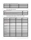
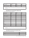
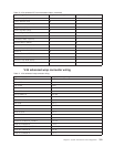
Notes:
1
Cable ID 0 is connected to common return pin 7 only at the DTE connector end and is not connected at the
DCE end.
2
The Select Standby signal (circuit 116) is not used on all V.24 Communication Adapter cable assemblies.
252 Service Functions V5R2