SCSI Functional Description 2-25
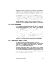
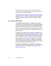
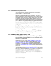
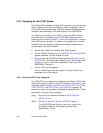
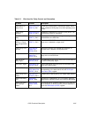
Table 2.3 Bits Used for Parity Control and Generation
Bit Name Location Description
Assert SATN/ on
Parity Errors
SCSI Control Zero
(SCNTL0),Bit1
Causes the LSI53C875A to automatically assert SATN/
when it detects a SCSI parity error while operating as an
initiator.
Enable Parity
Checking
SCSI Control Zero
(SCNTL0),Bit3
Enables the LSI53C875A to check for parity errors. The
LSI53C875A checks for odd parity.
Assert Even SCSI
Parity
SCSI Control One
(SCNTL1),Bit2
Determines the SCSI parity sense generated by the
LSI53C875A to the SCSI bus.
Disable Halt on
SATN/ or a Parity
Error (Target Mode
Only)
SCSI Control One
(SCNTL1),Bit5
Causes the LSI53C875A not to halt operations when a
parity error is detected in target mode.
Enable Parity Error
Interrupt
SCSI Interrupt
Enable Zero
(SIEN0),Bit0
Determines whether the LSI53C875A generates an
interrupt when it detects a SCSI parity error.
Parity Error SCSI Interrupt
Status Zero
(SIST0),Bit0
This status bit is set whenever the LSI53C875A detects a
parity error on the SCSI bus.
Status of SCSI
Parity Signal
SCSI Status Zero
(SSTAT0),Bit0
This status bit represents the active HIGH current state of
the SCSI SDP0 parity signal.
SCSI SDP1 Signal SCSI Status Two
(SSTAT2),Bit0
This bit represents the active HIGH current state of the
SCSI SDP1 parity signal.
Latched SCSI Parity SSTAT 2, Bit 3 and
SCSI Status One
(SSTAT1),Bit3
These bits reflect the SCSI odd parity signal
corresponding to the data latched into the SCSI Input
Data Latch (SIDL) register.
Master Parity Error
Enable
Chip Test Four
(CTEST4),Bit3
Enables parity checking during PCI master data phases.
Master Data Parity
Error
DMA Status
(DSTAT),Bit6
Set when the LSI53C875A
, as a PCI master, detects a
target device signaling a parity error during a data phase.
Master Data Parity
Error Interrupt
Enable
DMA Interrupt
Enable (DIEN),
Bit 6
By clearing this bit, a Master Data Parity Error does not
cause assertion of INTA/ (or INTB/), but the status bit is
set in the DMA Status (DSTAT) register.


