


3-14 Signal Descriptions
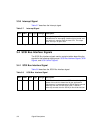
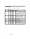
3.9 MAD Bus Programming
The MAD[7:0] pins, in addition to serving as the address/data bus for the
local memory interface, also are used to program power-up options for
the chip. A particular option is programmed allowing the internal
pull-down current sink to pull the pin LOW at reset or by connecting a
4.7 k
Ω resistor between the appropriate MAD[x] pin and V
SS
.The
pull-down resistors require that HC or HCT external components are
used for the memory interface. The MAD[7:0] pins are sensed by internal
circuitry three PCI clock cycles after RST/ is deasserted.
• MAD[7] Serial EEPROM programmable option. When allowed to be
pulled LOW by the internal pull-down current sink, the automatic data
download is enabled. When pulled HIGH by an external resistor, the
automatic data download is disabled. Please see Section 2.4, “Serial
EEPROM Interface,” in Chapter 2 and Subsystem ID and Subsystem
Vendor ID registers in Chapter 4 for additional information.
• MAD[6:4] Reserved and may be left floating.
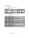
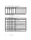
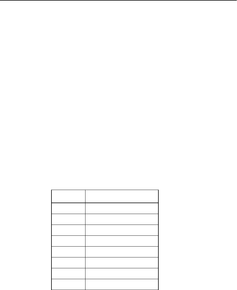
• The MAD[3:1] pins are used to set the size of the external expansion
ROM device attached. Encoding for these pins are listed in
Table 3.1 5 (“0” indicates a pull-down resistor is attached, “1”
indicates a pull-up resistor is attached).
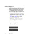
Table 3.15 Decode of MAD Pins
MAD[3:1] Available Memory Space
000 16 Kbyte
001 32 Kbyte
010 64 Kbyte
011 128 Kbyte
100 256 Kbyte
101 512 Kbyte
110 1024 Kbyte
111 no external memory present