


SCSI Functional Description 2-29
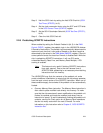
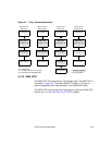
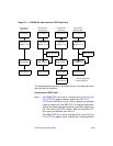
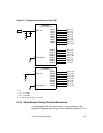
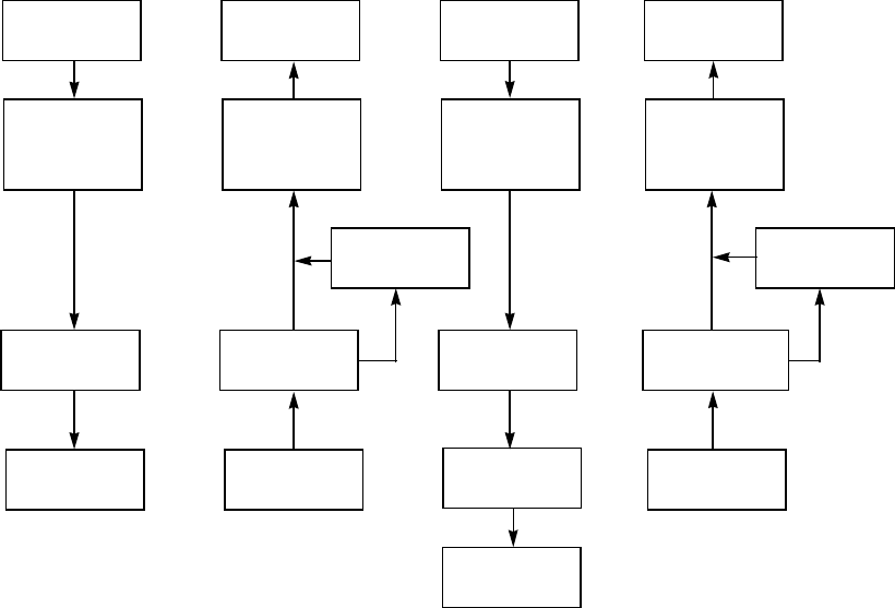
Figure 2.4 LSI53C875A Host Interface SCSI Data Paths
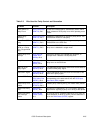
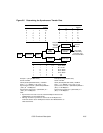
The following steps determine if any bytes remain in the data path when
the chip halts an operation:
Asynchronous SCSI Send –
Step 1. If the DMA FIFO size is set to 112 bytes (bit 5 of the Chip Test
Five (CTEST5) register cleared), look at the DMA FIFO
(DFIFO) and DMA Byte Counter (DBC) registers and calculate
if there are bytes left in the DMA FIFO. To make this calculation,
subtract the seven least significant bits of the DBC register from
the 7-bit value of the DFIFO register. AND the result with 0x7F
for a byte count between zero and 112.
If the DMA FIFO size is set to 944 bytes (bit 5 of the Chip Test
Five (CTEST5) register is set), subtract the 10 least significant
PCI Interface**
PCI Interface**
PCI Interface**
PCI Interface**
DMA FIFO*
(8 Bytes x 118)
DMA FIFO*
(8 Bytes x 118)
DMA FIFO*
(8 Bytes x 118)
DMA FIFO*
(8 Bytes x 118)
SODL Register*
SIDL Register*
SODL Register*
SCSI FIFO**
(1 or 2 Bytes x 31)
SCSI Interface**
SCSI Interface**
SODR Register* SCSI Interface**
SCSI Interface**
Asynchronous
SCSI Send
Asynchronous
SCSI Receive
Synchronous
SCSI Send
Synchronous
SCSI Receive
SWIDE Register
SWIDE Register
** = Parity protected
* = No parity protection