Power Management 2-51
2.4.2 No Download Mode
When MAD7 is pulled up through an external resistor, the automatic
download is disabled and no data is automatically loaded into chip
registers at power-up. The Subsystem ID and Subsystem Vendor ID
registers are read only, per the PCI specification, with a default value of
0x1000 and 0x1000 respectively.
2.5 Power Management
The LSI53C875A complies with the PCI Bus Power Management
Interface Specification, Revision 1.1. The PCI Function Power States D0,
D1, D2, and D3 are defined in that specification.
D0 is the maximum powered state, and D3 is the minimum powered
state. Power state D3 is further categorized as D3hot or D3cold. A
function that is powered off is said to be in the D3cold power state.
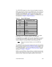
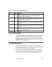
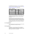
Table 2.7 Mode A Serial EEPROM Data Format
Byte Name Description
0xFB SVID(0) Subsystem Vendor ID, LSB. This byte is loaded into the least significant
byte of the Subsystem Vendor ID register in the appropriate PCI
configuration space at chip power-up.
0xFC SVID(1) Subsystem Vendor ID, MSB. This byte is loaded into the most significant
byte of the Subsystem Vendor ID register in the appropriate PCI
configuration space at chip power-up.
0xFD SID(0) Subsystem ID, LSB. This byte is loaded into the least significant byte of
the Subsystem ID register in the appropriate PCI configuration space at
chip power-up.
0xFE SID(1) Subsystem ID, MSB. This byte is loaded into the most significant byte of
the Subsystem ID register in the appropriate PCI configuration space at
chip power-up.
0xFF CKSUM Checksum. This 8-bit checksum is formed by adding, bytewise, each byte
contained in locations 0x00–0x03 to the seed value 0x55, and then taking
the 2s complement of the result.
0x100–0xEOM UD User Data.


