


Signal Descriptions 3-3
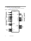
3.2 Signal Descriptions
The Signal Descriptions are divided into PCI Bus Interface Signals, SCSI
Bus Interface Signals, GPIO Signals, ROM Flash and Memory Interface
Signals, Test Interface Signals,andPower and Ground Signals.
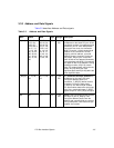
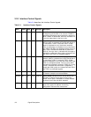
The PCI Bus Interface Signals are subdivided into System Signals,
Address and Data Signals, Interface Control Signals, Arbitration Signals,
Error Reporting Signals, and Interrupt Signal.
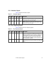
The SCSI Bus Interface Signals are subdivided into SCSI Bus Interface
Signals, SCSI Signals,andSCSI Control Signals.
Signals are assigned a type. There are five signal types:
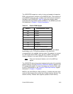
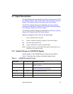
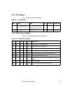
3.2.1 Internal Pull-ups on LSI53C875A Signals
Several signals in the LSI53C875A have internal pull-up resistors.
Table 3.1 describes the conditions that enable these pull-ups.
I Input, a standard input only signal.
O Output, a standard output driver (typically a Totem Pole Output).
I/O Input and output (bidirectional).
T/S 3-state, a bidirectional, 3-state input/output signal.
S/T/S Sustained 3-state, an active LOW 3-state signal owned and driven by
one and only one agent at a time.
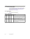
Table 3.1 LSI53C875A Internal Pull-ups
Signal Name Pull-up Current Conditions for Pull-up
IRQ/ 25 µA Pull-up enabled when the IRQ mode bit (bit 3 of DCNTL
(0x3B)) is cleared.
GPIO[1:0] 25 µA Pull-up enabled when bits [1:0] of General Purpose Pin
Control Zero (GPCNTL0) are not set.
TEST_HSC/ 25 µA Pull-up enabled all the time.
TEST_RST/ 25 µA Pull-up enabled all the time.
TRST,TCK,TMS,TDI 25µA Pull-up enabled all the time.