


EliteMail VMS/EliteMail Limited Issue 3
Hardware Specifications 2 - 5
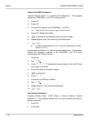
S
ECTION
5
I
NSTALL
M
ODEM
K
IT
U
NIT
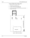
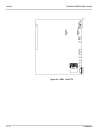
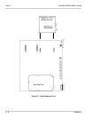
The Modem Kit Unit provides remote connection. To install the Modem Kit
Unit refer to Figure 2-3 Install Modem Kit Unit. The VMS( )-U10 ETU is
shown, but the Modem Kit Unit can also be installed in connectors J2 and
J3 on the FMS( )-U10 ETU.
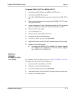
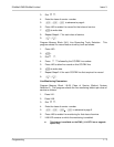
1. Verify that the HDD LED on the VMS/FMS( )-U10 ETU is off.
2. Verify that the BCLR LED is green.
3. Turn off the MB (Make Busy) Switch and verify that MB LED is Off.
4. Wear a grounding strap when removing the ETU from the Electra
Elite KSU.
5. Locate connectors J2 and J3 on the right side of the ETU, and press
down the Modem Kit Unit board until a secure connection is made. If
changing from local to remote connection, place DIP switch SW1,
position 3 down (On).
When DIP switch SW1, position 3 is on, COM1 cannot be used for
direct connection.
6. Return the ETU to the KSU.
7. Turn the MB Switch on.
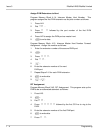
T
he
Modem Kit Unit
must be used behind an Electra Elite system with
an SLI(8) -U10 ETU or SLT(1)-U10 ADP. It is not approved for FCC
Part 68 and UL 1459; therefore, it should not be directly connected to
the PSTN (CO line)
.
FCC Part 68 and UL1459