


GS700TR Smart Switch Software Administration Manual
3-26 Configuring Switching Information
v1.0, May, 2008
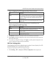
3. Click Refresh to update the information on the screen with the most current data.
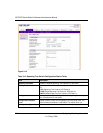
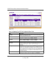
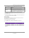
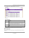
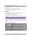
Rapid STP Configuration
Use the Rapid Spanning Tree Configuration page to configure Rapid Spanning Tree (RSTP) on the
switch.
To display the Rapid STP Configuration page:
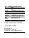
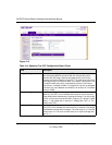
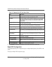
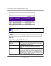
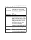
Table 3-17. Spanning Tree CST Port Status Fields
Field Description
Interface Select a physical or port channel interface to configure. The port is
associated with the VLAN(s) associated with the CST.
Port Role Each MST Bridge Port that is enabled is assigned a Port Role for each
spanning tree. The port role will be one of the following values: Root
Port, Designated Port, Alternate Port, Backup Port, Master Port or
Disabled Port.
Designated Root Root Bridge for the CST. It is made up using the bridge priority and the
base MAC address of the bridge.
Designated Cost Displays cost of the port participating in the STP topology. Ports with a
lower cost are less likely to be blocked if STP detects loops.
Designated Bridge Bridge Identifier of the bridge with the Designated Port. It is made up
using the bridge priority and the base MAC address of the bridge.
Designated Port Port Identifier on the Designated Bridge that offers the lowest cost to the
LAN. It is made up from the port priority and the interface number of the
port.
Topology Change
Acknowledge
Identifies whether the next BPDU to be transmitted for this port would
have the topology change acknowledgement flag set. It is either “True”
or “False”.
Edge Port Indicates whether the port is enabled as an edge port. Possible values
are Enabled or Disabled.
Point-to-point MAC Derived value of the point-to-point status.
CST Regional Root Shows the bridge priority and base MAC address of the CST Regional
Root.
CST Path Cost Shows the path Cost to the CST tree Regional Root.
Port Forwarding State Displays the Forwarding State of this port.