Basic Clock Module Operation
4-7
Basic Clock Module
Adjusting the DCO frequency
After a PUC, the internal resistor is selected for the DC generator, RSELx =
4, and DCOx = 3, allowing the DCO to start at a mid-range frequency. MCLK
and SMCLK are sourced from DCOCLK. Because the CPU executes code
from MCLK, which is sourced from the fast-starting DCO, code execution
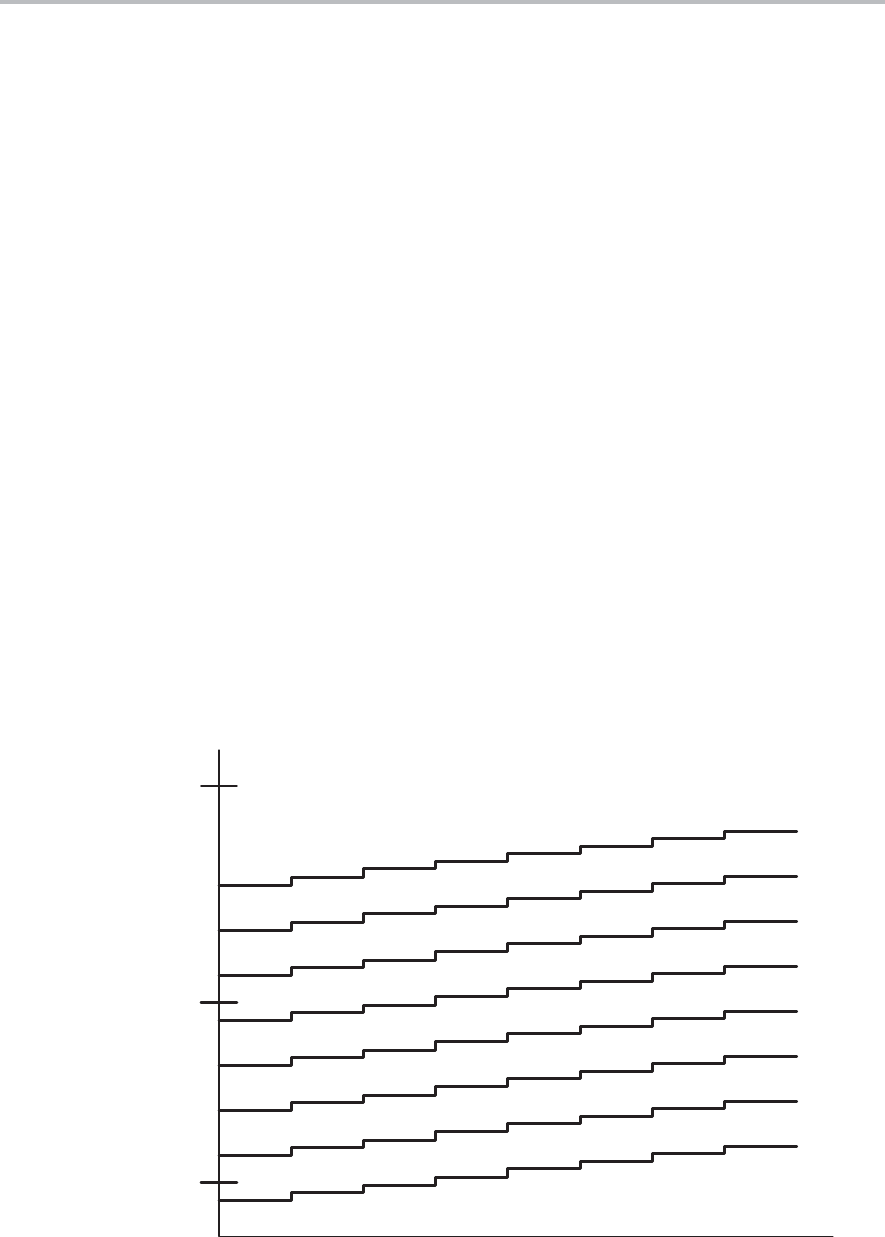
begins from PUC in less than 6 µs. The typical DCOx and RSELx ranges and
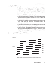
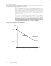
steps are shown in Figure 4−5.
The frequency of DCOCLK is set by the following functions:
- The current injected into the DC generator by either the internal or external
resistor defines the fundamental frequency. The DCOR bit selects the
internal or external resistor.
- The three RSELx bits select one of eight nominal frequency ranges for the
DCO. These ranges are defined for an individual device in the
device-specific data sheet.
- The three DCOx bits divide the DCO range selected by the RSELx bits into
8 frequency steps, separated by approximately 10%.
- The five MODx bits, switch between the frequency selected by the DCOx
bits and the next higher frequency set by DCOx+1. When DCOx = 07h,
the MODx bits have no effect because the DCO is already at the highest
setting for the selected RSELx range.
Figure 4−5. Typical DCOx Range and RSELx Steps
RSEL=0
RSEL=1
RSEL=2
RSEL=3
RSEL=4
RSEL=5
RSEL=6
RSEL=7
DCO=0 DCO=7DCO=4DCO=1 DCO=2 DCO=3 DCO=5 DCO=6
f
DCO
1000 kHz
10000 kHz
100 kHz


