


I
2
C Module Registers
15-22
USART Peripheral Interface, I
2
C Mode
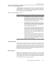
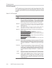
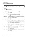
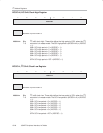
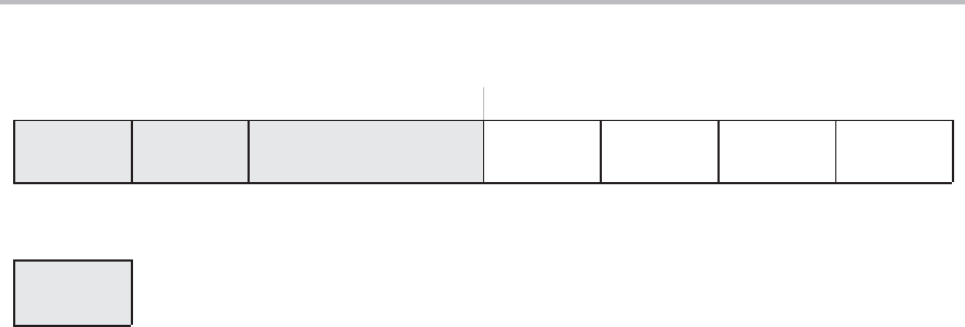
I2CTCTL, I
2
C Transmit Control Register
76543210
I2CWORD I2CRM I2CSSELx I2CTRX I2CSTB I2CSTP I2CSTT
rw−0 rw−0 rw−0 rw−0 rw−0 rw−0 rw−0 rw−0
Modifiable only when I2CEN = 0
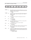
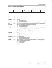
I2CWORD
Bit 7 I
2
C word mode. Selects byte or word mode for the I
2
C data register.
0 Byte mode
1 Word mode
I2CRM
Bit 6 I
2
C repeat mode
0 I2CNDAT defines the number of bytes transmitted.
1 Number of bytes transmitted is controlled by software. I2CNDAT is
unused.
I2CSSELx
Bits
5−4
I
2
C clock source select. When MST = 1 and arbitration is lost, the external SCL
signal is automatically used.
00 No clock − I
2
C module is inactive
01 ACLK
10 SMCLK
11 SMCLK
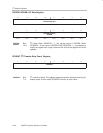
I2CTRX
Bit 3 I
2
C transmit. This bit selects the transmit or receive function for the I
2
C
controller when MST = 1. When MST = 0, the R/W bit of the address byte
defines the data direction. I2CTRX must be reset for proper slave mode
operation.
0 Receive mode. Data is received on the SDA pin.
1 Transmit mode. Data transmitted on the SDA pin.
I2CSTB
Bit 2 Start byte. Setting the I2CSTB bit when MST = 1 initiates a start byte when
I2CSTT = 1. After the start byte is initiated, I2CSTB is automatically cleared.
0: No action
1: Send START condition and start byte (01h), but no STOP condition.
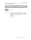
I2CSTP
Bit 1 STOP bit. This bit is used to generate STOP condition. After the STOP
condition, the I2CSTP is automatically cleared.
0: No action
1: Send STOP condition
I2CSTT
Bit 0 START bit. This bit is used to generate a START condition. After the start
condition the I2CSTT is automatically cleared.
0: No action
1: Send START condition