


USART Operation: SPI Mode
14-5
USART Peripheral Interface, SPI Mode
14.2.2 Master Mode
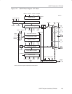
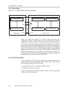
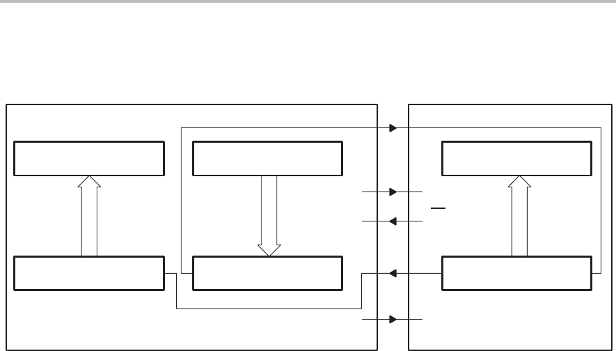
Figure 14−2. USART Master and External Slave
Receive Buffer UxRXBUF
Receive Shift Register
MSB
LSB
Transmit Buffer UxTXBUF
Transmit Shift Register
MSB
LSB
SPI Receive Buffer
Data Shift Register (DSR)
MSB
LSB
SOMI SOMI
SIMO SIMO
MASTER SLAVE
Px.x STE
STE
SS
Port.x
UCLK
SCLK
MSP430 USART COMMON SPI
Figure 14−2 shows the USART as a master in both 3-pin and 4-pin
configurations. The USART initiates data transfer when data is moved to the
transmit data buffer UxTXBUF. The UxTXBUF data is moved to the TX shift
register when the TX shift register is empty, initiating data transfer on SIMO
starting with the most-significant bit. Data on SOMI is shifted into the receive
shift register on the opposite clock edge, starting with the most-significant bit.
When the character is received, the receive data is moved from the RX shift
register to the received data buffer UxRXBUF and the receive interrupt flag,
URXIFGx, is set, indicating the RX/TX operation is complete.
A set transmit interrupt flag, UTXIFGx, indicates that data has moved from
UxTXBUF to the TX shift register and UxTXBUF is ready for new data. It does
not indicate RX/TX completion.
To receive data into the USART in master mode, data must be written to
UxTXBUF because receive and transmit operations operate concurrently.
Four-Pin SPI Master Mode
In 4-pin master mode, STE is used to prevent conflicts with another master.
The master operates normally when STE is high. When STE is low:
- SIMO and UCLK are set to inputs and no longer drive the bus
- The error bit FE is set indicating a communication integrity violation to be
handled by the user
A low STE signal does not reset the USART module. The STE input signal is
not used in 3-pin master mode.