


System Reset and Initialization
2-13
System Resets, Interrupts, and Operating Modes
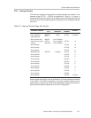
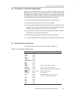
2.2.4 Interrupt Vectors
The interrupt vectors and the power-up starting address are located in the
address range 0FFFFh − 0FFE0h as described in Table 2−1. A vector is
programmed by the user with the 16-bit address of the corresponding interrupt
service routine. See the device-specific data sheet for the complete interrupt
vector list.
Table 2−1.Interrupt Sources,Flags, and Vectors
INTERRUPT SOURCE
INTERRUPT
FLAG
SYSTEM
INTERRUPT
WORD
ADDRESS
PRIORITY
Power-up, external
reset, watchdog,
flash password
WDTIFG
KEYV
Reset 0FFFEh 15, highest
NMI, oscillator fault,
flash memory access
violation
NMIIFG
OFIFG
ACCVIFG
(non)-maskable
(non)-maskable
(non)-maskable
0FFFCh 14
device-specific 0FFFAh 13
device-specific 0FFF8h 12
device-specific 0FFF6h 11
Watchdog timer WDTIFG maskable 0FFF4h 10
device-specific 0FFF2h 9
device-specific 0FFF0h 8
device-specific 0FFEEh 7
device-specific 0FFECh 6
device-specific 0FFEAh 5
device-specific 0FFE8h 4
device-specific 0FFE6h 3
device-specific 0FFE4h 2
device-specific 0FFE2h 1
device-specific
0FFE0h 0, lowest
Some module enable bits, interrupt enable bits, and interrupt flags are located
in the SFRs. The SFRs are located in the lower address range and are
implemented in byte format. SFRs must be accessed using byte instructions.
See the device-specific datasheet for the SFR configuration.