


ADC12 Operation
17-6
ADC12
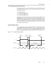
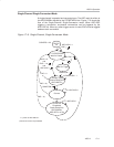
17.2.3 Voltage Reference Generator
The ADC12 module contains a built-in voltage reference with two selectable
voltage levels, 1.5 V and 2.5 V. Either of these reference voltages may be used
internally and externally on pin V
REF+
.
Setting REFON=1 enables the internal reference. When REF2_5V = 1, the
internal reference is 2.5 V, the reference is 1.5 V when REF2_5V = 0. The
reference can be turned off to save power when not in use.
For proper operation the internal voltage reference generator must be
supplied with storage capacitance across V
REF+
and A
VSS
. The recommended
storage capacitance is a parallel combination of 10-
µF and 0.1-µF capacitors
.
From turn-on, a maximum of 17 ms must be allowed for the voltage reference
generator to bias the recommended storage capacitors. If the internal
reference generator is not used for the conversion, the storage capacitors are
not required.
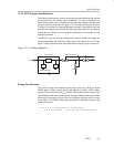
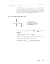
Note: Reference Decoupling
Approximately 200
µA is required from any reference used by the ADC12
while the two LSBs are being resolved during a conversion. A parallel
combination of 10-
µF and 0.1-µF capacitors is recommended for any
reference used as shown in Figure 17−11.
External references may be supplied for V
R+
and V
R−
through pins Ve
REF+
and
V
REF−
/Ve
REF−
respectively.
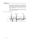
17.2.4 Auto Power-Down
The ADC12 is designed for low power applications. When the ADC12 is not
actively converting, the core is automatically disabled and automatically
re-enabled when needed. The ADC12OSC is also automatically enabled
when needed and disabled when not needed. The reference is not
automatically disabled, but can be disabled by setting REFON = 0. When the
core, oscillator, or reference are disabled, they consume no current.