Basic Clock Module Operation
4-9
Basic Clock Module
4.2.5 DCO Modulator
The modulator mixes two DCO frequencies, f
DCO
and f
DCO+1
to produce an
intermediate effective frequency between f
DCO
and f
DCO+1
and spread the
clock energy, reducing electromagnetic interference (EMI)
.
The modulator
mixes f
DCO
and f
DCO+1
for 32 DCOCLK clock cycles and is configured with the
MODx bits. When MODx = 0 the modulator is off.
The modulator mixing formula is:
t =(32− MODx) × t
DCO
+ MODx × t
DCO+1
Because f
DCO
is lower than the effective frequency and f
DCO+1
is higher than
the effective frequency, the error of the effective frequency integrates to zero.
It does not accumulate. The error of the effective frequency is zero every 32
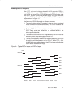
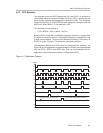
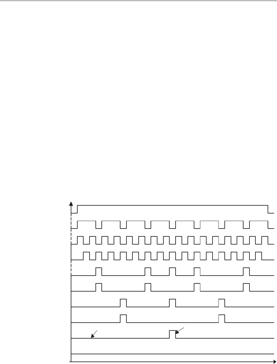
DCOCLK cycles. Figure 4−7 illustrates the modulator operation.
The modulator settings and DCO control are configured with software. The
DCOCLK can be compared to a stable frequency of known value and adjusted
with the DCOx, RSELx, and MODx bits. See http://www.msp430.com for
application notes and example code on configuring the DCO.
Figure 4−7. Modulator Patterns
MODx
Lower DCO Tap Frequency f
DCO
31
24
16
15
5
4
3
2
1
0
Upper DCO Tap Frequency f
DCO+1


