


ADC10 Registers
18-25
ADC10
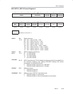
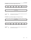
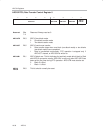
ADC10CTL0, ADC10 Control Register 0
15 14 13 12 11 10 9 8
SREFx ADC10SHTx ADC10SR REFOUT REFBURST
rw−(0) rw−(0) rw−(0) rw−(0) rw−(0) rw−(0) rw−(0) rw−(0)
76543210
MSC REF2_5V REFON ADC10ON ADC10IE ADC10IFG ENC ADC10SC
rw−(0) rw−(0) rw−(0) rw−(0) rw−(0) rw−(0) rw−(0) rw−(0)
Modifiable only when ENC = 0
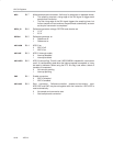
SREFx
Bits
15-13
Select reference
000 V
R+
= V
CC
and V
R−
= V
SS
001 V
R+
= V
REF+
and V
R−
= V
SS
010 V
R+
= Ve
REF+
and V
R−
= V
SS
011 V
R+
= Ve
REF+
and V
R−
= V
SS
100 V
R+
= V
CC
and V
R−
= V
REF−
/ Ve
REF−
101 V
R+
= V
REF+
and V
R−
= V
REF−
/ Ve
REF−
110 V
R+
= Ve
REF+
and V
R−
= V
REF−
/ Ve
REF−
111 V
R+
= Ve
REF+
and V
R−
= V
REF−
/ Ve
REF−
ADC10
SHTx
Bits
12-11
ADC10 sample-and-hold time
00 4 x ADC10CLKs
01 8 x ADC10CLKs
10 16 x ADC10CLKs
11 64 x ADC10CLKs
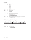
ADC10SR
Bit 10 ADC10 sampling rate. This bit selects the reference buffer drive capability for
the maximum sampling rate. Setting ADC10SR reduces the current
consumption of the reference buffer.
0 Reference buffer supports up to ~200 ksps
1 Reference buffer supports up to ~50 ksps
REFOUT
Bit 9 Reference output
0 Reference output off
1 Reference output on
REFBURST
Bit 8 Reference burst. REFOUT must also be set.
0 Reference buffer on continuously
1 Reference buffer on only during sample-and-conversion