


Timer_A Operation
11-13
Timer_A
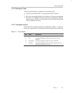
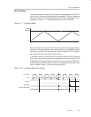
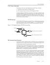
11.2.5 Output Unit
Each capture/compare block contains an output unit. The output unit is used
to generate output signals such as PWM signals. Each output unit has eight
operating modes that generate signals based on the EQU0 and EQUx signals.
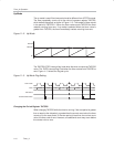
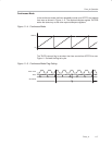
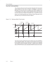
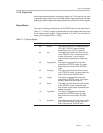
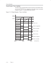
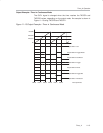
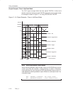
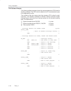
Output Modes
The output modes are defined by the OUTMODx bits and are described in
Table 11−2. The OUTx signal is changed with the rising edge of the timer clock
for all modes except mode 0. Output modes 2, 3, 6, and 7 are not useful for
output unit 0 because EQUx = EQU0.
Table 11−2.Output Modes
OUTMODx Mode Description
000 Output The output signal OUTx is defined by the
OUTx bit. The OUTx signal updates
immediately when OUTx is updated.
001 Set The output is set when the timer counts
to the TACCRx value. It remains set until
a reset of the timer, or until another
output mode is selected and affects the
output.
010 Toggle/Reset The output is toggled when the timer
counts to the TACCRx value. It is reset
when the timer counts to the TACCR0
value.
011 Set/Reset The output is set when the timer counts
to the TACCRx value. It is reset when the
timer counts to the TACCR0 value.
100 Toggle The output is toggled when the timer
counts to the TACCRx value. The output
period is double the timer period.
101 Reset The output is reset when the timer counts
to the TACCRx value. It remains reset
until another output mode is selected and
affects the output.
110 Toggle/Set The output is toggled when the timer
counts to the TACCRx value. It is set
when the timer counts to the TACCR0
value.
111 Reset/Set The output is reset when the timer counts
to the TACCRx value. It is set when the
timer counts to the TACCR0 value.