


I
2
C Module Registers
15-21
USART Peripheral Interface, I
2
C Mode
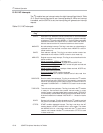
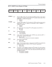
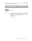
U0CTL, USART0 Control Register-I
2
C Mode
76543210
RXDMAEN TXDMAEN I2C XA LISTEN SYNC MST I2CEN
rw−0 rw−0 rw−0 rw−0 rw−0 rw−0 rw−0 rw−1
RXDMAEN
Bit 7 Receive DMA enable. This bit enables the DMA controller to be used to
transfer data from the I
2
C module after the I
2
C modules receives data. When
RXDMAEN = 1, RXRDYIE is ignored.
0 Disabled
1 Enabled
TXDMAEN
Bit 6 Transmit DMA enable. This bit enables the DMA controller to be used to
provide data to the I
2
C module for transmission. When TXDMAEN = 1,
TXRDYIE, is ignored.
0 Disabled
1 Enabled
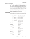
I2C
Bit 5 I
2
C mode enable. This bit select I
2
C or SPI operation when SYNC = 1.
0 SPI mode
1I
2
C mode
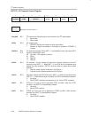
XA
Bit 4 Extended Addressing
0 7-bit addressing
1 10-bit addressing
LISTEN
Bit 3 Listen. This bit selects loopback mode. LISTEN is only valid when MST = 1
and I2CTRX = 1 (master transmitter).
0 Normal mode
1 SDA is internally fed back to the receiver (loopback).
SYNC
Bit 2 Synchronous mode enable
0 UART mode
1 SPI or I
2
C mode
MST
Bit 1 Master. This bit selects master or slave mode. The MST bit is automatically
cleared when arbitration is lost or a STOP condition is generated.
0 Slave mode
1 Master mode
I2CEN
Bit 0 I
2
C enable. The bit enables or disables the I
2
C module. The initial condition
for this bit is set, and SWRST function for UART or SPI. When the I2C and
SYNC bits are first set after a PUC, this bit becomes I2CEN function and is
automatically cleared.
0I
2
C operation is disabled
1I
2
C operation is enabled