


Timer_B Operation
12-11
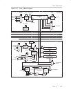
Timer_B
12.2.4 Capture/Compare Blocks
Three or seven identical capture/compare blocks, TBCCRx, are present in
Timer_B. Any of the blocks may be used to capture the timer data or to
generate time intervals.
Capture Mode
The capture mode is selected when CAP = 1. Capture mode is used to record
time events. It can be used for speed computations or time measurements.
The capture inputs CCIxA and CCIxB are connected to external pins or internal
signals and are selected with the CCISx bits. The CMx bits select the capture
edge of the input signal as rising, falling, or both. A capture occurs on the
selected edge of the input signal. If a capture is performed:
- The timer value is copied into the TBCCRx register
- The interrupt flag CCIFG is set
The input signal level can be read at any time via the CCI bit. MSP430x1xx
family devices may have different signals connected to CCIxA and CCIxB.
Refer to the device-specific datasheet for the connections of these signals.
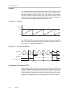
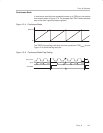
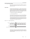
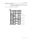
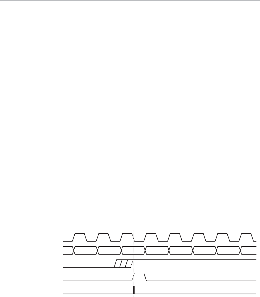
The capture signal can be asynchronous to the timer clock and cause a race
condition. Setting the SCS bit will synchronize the capture with the next timer
clock. Setting the SCS bit to synchronize the capture signal with the timer clock
is recommended. This is illustrated in Figure 12−10.
Figure 12−10. Capture Signal (SCS=1)
n−2 n−1
Timer Clock
Timer
Set TBCCRx CCIFG
n+1 n+3 n+4
CCI
Capture
n+2n
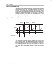
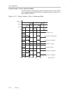
Overflow logic is provided in each capture/compare register to indicate if a
second capture was performed before the value from the first capture was
read. Bit COV is set when this occurs as shown in Figure 12−11. COV must
be reset with software.