


USART Operation: SPI Mode
14-9
USART Peripheral Interface, SPI Mode
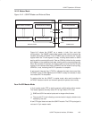
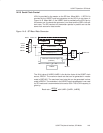
14.2.5 Serial Clock Control
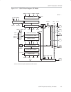
UCLK is provided by the master on the SPI bus. When MM = 1, BITCLK is
provided by the USART baud rate generator on the UCLK pin as shown in
Figure 14−8. When MM = 0, the USART clock is provided on the UCLK pin by
the master and, the baud rate generator is not used and the SSELx bits are
don’t care. The SPI receiver and transmitter operate in parallel and use the
same clock source for data transfer.
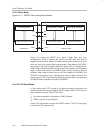
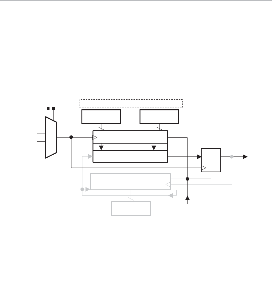
Figure 14−8. SPI Baud Rate Generator
Bit Start
mX
BRCLK
88
UCLKI
ACLK
SMCLK
SMCLK
11
BITCLK
10
01
00
2
0
2
7
2
8
2
15
Compare (0 or 1)
Modulation Data Shift Register
(LSB first)
16−Bit Counter
Q0
............
Q15
m0m7
...
...
8
UxBR1 UxBR0
Toggle
FF
N =
R
R
R
UxMCTL
SSEL1 SSEL0
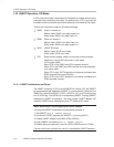
The 16-bit value of UxBR0+UxBR1 is the division factor of the USART clock
source, BRCLK. The maximum baud rate that can be generated in master
mode is BRCLK/2. The maximum baud rate that can be generated in slave
mode is BRCLK. The modulator in the USART baud rate generator is not used
for SPI mode and is recommended to be set to 000h. The UCLK frequency is
given by:
Baud rate =
BRCLK
UxBR
with UxBR= [UxBR1, UxBR0]