


I
2
C Module Introduction
15-2
USART Peripheral Interface, I
2
C Mode
15.1 I
2
C Module Introduction
The inter-IC control (I
2
C) module provides an interface between the MSP430
and I
2
C-compatible devices connected by way of the two-wire I
2
C serial bus.
External components attached to the I
2
C bus serially transmit and/or receive
serial data to/from the USART through the 2-wire I
2
C interface.
The I
2
C module has the following features:
- Compliance to the Philips Semiconductor I
2
C specification v2.1
J Byte/word format transfer
J 7-bit and 10-bit device addressing modes
J General call
J START/RESTART/STOP
J Multi-master transmitter/slave receiver mode
J Multi-master receiver/slave transmitter mode
J Combined master transmit/receive and receive/transmit mode
J Standard mode up to100 kbps and fast mode up to 400 kbps support
- Built-in FIFO for buffered read and write
- Programmable clock generation
- 16-bit wide data access to maximize bus throughput
- Automatic data byte counting
- Designed for low power
- Slave receiver START detection for auto-wake up from LPMx modes
- Extensive interrupt capability
- Implemented on USART0 only
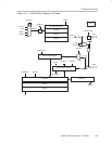
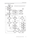
The I
2
C block diagram is shown in Figure 15−1.