


ADC10 Operation
18-20
ADC10
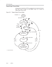
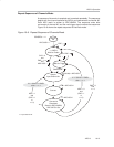
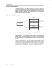
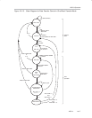
Continuous Transfer
A continuous transfer is selected if ADC10CT bit is set. The DTC will not stop
after block one in (one-block mode) or block two (two-block mode) has been
transferred. The internal address pointer and transfer counter are set equal to
ADC10SA and n respectively. Transfers continue starting in block one. If the
ADC10CT bit is reset, DTC transfers cease after the current completion of
transfers into block one (in the one-block mode) or block two (in the two-block
mode) have been transfer.
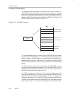
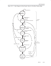
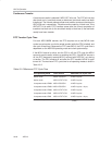
DTC Transfer Cycle Time
For each ADC10MEM transfer, the DTC requires one or two MCLK clock
cycles to synchronize, one for the actual transfer (while the CPU is halted), and
one cycle of wait time. Because the DTC uses MCLK, the DTC cycle time is
dependent on the MSP430 operating mode and clock system setup.
If the MCLK source is active, but the CPU is off, the DTC uses the MCLK
source for each transfer, without re-enabling the CPU. If the MCLK source is
off, the DTC temporarily restarts MCLK, sourced with DCOCLK, only during
a transfer. The CPU remains off and after the DTC transfer, MCLK is again
turned off. The maximum DTC cycle time for all operating modes is show in
Table 18−2.
Table 18−2.Maximum DTC Cycle Time
CPU Operating Mode Clock Source Maximum DTC Cycle Time
Active mode MCLK=DCOCLK 3 MCLK cycles
Active mode MCLK=LFXT1CLK 3 MCLK cycles
Low-power mode LPM0/1 MCLK=DCOCLK 4 MCLK cycles
Low-power mode LPM3/4 MCLK=DCOCLK 4 MCLK cycles + 6 µs
†
Low-power mode LPM0/1 MCLK=LFXT1CLK 4 MCLK cycles
Low-power mode LPM3 MCLK=LFXT1CLK 4 MCLK cycles
Low-power mode LPM4 MCLK=LFXT1CLK
4 MCLK cycles + 6 µs
†
†
The additional 6 µs are needed to start the DCOCLK. It is the t
(LPMx)
parameter in the datasheet.