8-8
Block Transfers
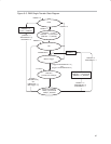
In block transfer mode, a transfer of a complete block of data occurs after one
trigger. When DMADTx = 1, the DMAEN bit is cleared after the completion of
the block transfer and must be set again before another block transfer can be
triggered. After a block transfer has been triggered, further trigger signals
occurring during the block transfer are ignored. The block transfer state
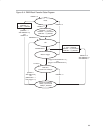
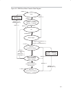
diagram is shown in Figure 8−4.
The DMAxSZ register is used to define the size of the block and the
DMADSTINCRx and DMASRCINCRx bits select if the destination address
and the source address are incremented or decremented after each transfer
of the block. If DMAxSZ = 0, no transfers occur.
The DMAxSA, DMAxDA, and DMAxSZ registers are copied into temporary
registers. The temporary values of DMAxSA and DMAxDA are incremented
or decremented after each transfer in the block. The DMAxSZ register is
decremented after each transfer of the block and shows the number of
transfers remaining in the block. When the DMAxSZ register decrements to
zero it is reloaded from its temporary register and the corresponding DMAIFG
flag is set.
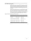
During a block transfer, the CPU is halted until the complete block has been
transferred. The block transfer takes 2 x MCLK x DMAxSZ clock cycles to
complete. CPU execution resumes with its previous state after the block
transfer is complete.
In repeated block transfer mode, the DMAEN bit remains set after completion
of the block transfer. The next trigger after the completion of a repeated block
transfer triggers another block transfer.


