


Digital I/O Operation
9-4
Digital I/O
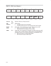
9.2.4 Function Select Registers PxSEL
Port pins are often multiplexed with other peripheral module functions. See the
device-specific data sheet to determine pin functions. Each PxSEL bit is used
to select the pin function − I/O port or peripheral module function.
Bit = 0: I/O Function is selected for the pin
Bit = 1: Peripheral module function is selected for the pin
Setting PxSELx = 1 does not automatically set the pin direction. Other
peripheral module functions may require the PxDIRx bits to be configured
according to the direction needed for the module function. See the pin
schematics in the device-specific datasheet.
;Output ACLK on P2.0 on MSP430F11x1
BIS.B #01h,&P2SEL ; Select ACLK function for pin
BIS.B #01h,&P2DIR ; Set direction to output *Required*
Note: P1 and P2 Interrupts Are Disabled When PxSEL = 1
When any P1SELx or P2SELx bit is set, the corresponding pin’s interrupt
function is disabled. Therefore, signals on these pins will not generate P1 or
P2 interrupts, regardless of the state of the corresponding P1IE or P2IE bit.
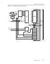
When a port pin is selected as an input to a peripheral, the input signal to the
peripheral is a latched representation of the signal at the device pin. While
PxSELx=1, the internal input signal follows the signal at the pin. However, if
the PxSELx=0, the input to the peripheral maintains the value of the input
signal at the device pin before the PxSELx bit was reset.