


DAC12 Registers
19-11
DAC12
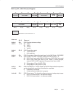
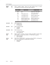
DAC12_xCTL, DAC12 Control Register
15 14 13 12 11 10 9 8
Reserved DAC12SREFx DAC12RES DAC12LSELx
DAC12
CALON
DAC12IR
rw−(0) rw−(0) rw−(0) rw−(0) rw−(0) rw−(0) rw−(0) rw−(0)
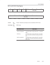
76543210
DAC12AMPx DAC12DF DAC12IE DAC12IFG DAC12ENC
DAC12
GRP
rw−(0) rw−(0) rw−(0) rw−(0) rw−(0) rw−(0) rw−(0) rw−(0)
Modifiable only when DAC12ENC = 0
Reserved
Bit 15 Reserved
DAC12
SREFx
Bits
14-13
DAC12 select reference voltage
00 V
REF+
01 V
REF+
10 Ve
REF+
11 Ve
REF+
DAC12
RES
Bit 12 DAC12 resolution select
0 12-bit resolution
1 8-bit resolution
DAC12
LSELx
Bits
11-10
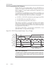
DAC12 load select. Selects the load trigger for the DAC12 latch. DAC12ENC
must be set for the DAC to update, except when DAC12LSELx = 0.
00 DAC12 latch loads when DAC12_xDAT written (DAC12ENC is ignored)
01 DAC12 latch loads when DAC12_xDAT written, or, when grouped,
when all DAC12_xDAT registers in the group have been written.
10 Rising edge of Timer_A.OUT1 (TA1)
11 Rising edge of Timer_B.OUT2 (TB2)
DAC12
CALON
Bit 9 DAC12 calibration on. This bit initiates the DAC12 offset calibration sequence
and is automatically reset when the calibration completes.
0 Calibration is not active
1 Initiate calibration/calibration in progress
DAC12IR
Bit 8 DAC12 input range. This bit sets the reference input and voltage output range.
0 DAC12 full-scale output = 3x reference voltage
1 DAC12 full-scale output = 1x reference voltage