


ADC10 Operation
18-15
ADC10
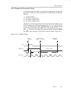
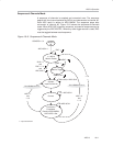
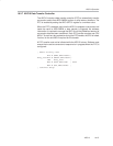
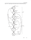
18.2.7 ADC10 Data Transfer Controller
The ADC10 includes a data transfer controller (DTC) to automatically transfer
conversion results from ADC10MEM to other on-chip memory locations. The
DTC is enabled by setting the ADC10DTC1 register to a nonzero value.
When the DTC is enabled, each time the ADC10 completes a conversion and
loads the result to ADC10MEM, a data transfer is triggered. No software
intervention is required to manage the ADC10 until the predefined amount of
conversion data has been transferred. Each DTC transfer requires one CPU
MCLK. To avoid any bus contention during the DTC transfer, the CPU is halted,
if active, for the one MCLK required for the transfer.
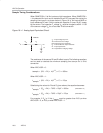
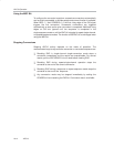
A DTC transfer must not be initiated while the ADC10 is busy. Software must
ensure that no active conversion or sequence is in progress when the DTC is
configured:
; ADC10 activity test
BIC.W #ENC,&ADC10CTL0 ;
busy_test BIT.W #BUSY,&ADC10CTL1;
JNZ busy_test ;
MOV.W #xxx,&ADC10SA ; Safe
MOV.B #xx,&ADC10DTC1 ;
; continue setup