


USART Operation: UART Mode
13-4
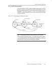
USART Peripheral Interface, UART Mode
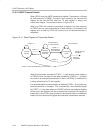
13.2 USART Operation: UART Mode
In UART mode, the USART transmits and receives characters at a bit rate
asynchronous to another device. Timing for each character is based on the
selected baud rate of the USART. The transmit and receive functions use the
same baud rate frequency.
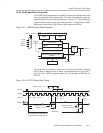
13.2.1 USART Initialization and Reset
The USART is reset by a PUC or by setting the SWRST bit. After a PUC, the
SWRST bit is automatically set, keeping the USART in a reset condition. When
set, the SWRST bit resets the URXIEx, UTXIEx, URXIFGx, RXWAKE,
TXWAKE, RXERR, BRK, PE, OE, and FE bits and sets the UTXIFGx and
TXEPT bits. The receive and transmit enable flags, URXEx and UTXEx, are
not altered by SWRST. Clearing SWRST releases the USART for operation.
See also chapter USART Module, I2C mode for USART0 when reconfiguring
from I
2
C mode to UART mode.
Note: Initializing or Re-Configuring the USART Module
The required USART initialization/re-configuration process is:
1) Set SWRST (BIS.B #SWRST,&UxCTL)
2) Initialize all USART registers with SWRST = 1 (including UxCTL)
3) Enable USART module via the MEx SFRs (URXEx and/or UTXEx)
4) Clear SWRST via software (BIC.B #SWRST,&UxCTL)
5) Enable interrupts (optional) via the IEx SFRs (URXIEx and/or UTXIEx)
Failure to follow this process may result in unpredictable USART behavior.
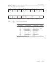
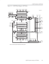
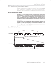
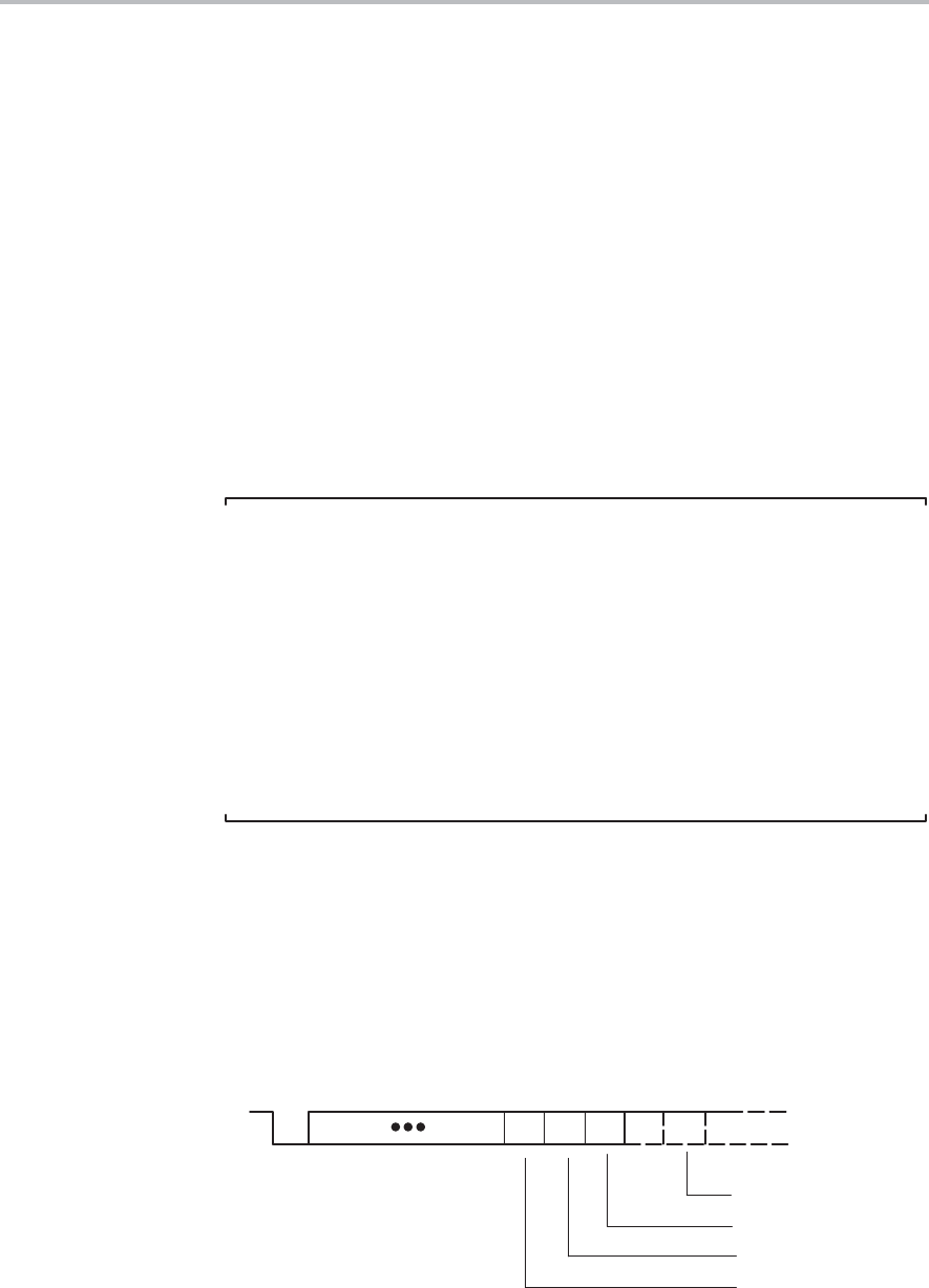
13.2.2 Character Format
The UART character format, shown in Figure 13−2, consists of a start bit,
seven or eight data bits, an even/odd/no parity bit, an address bit (address-bit
mode), and one or two stop bits. The bit period is defined by the selected clock
source and setup of the baud rate registers.
Figure 13−2. Character Format
[Parity Bit, PENA = 1]
[Address Bit, MM = 1]
Mark
Space
D0 D6 D7 AD PA SP SP
[Optional Bit, Condition]
[2nd Stop Bit, SP = 1]
[8th Data Bit, CHAR = 1]
ST