


Timer_A Operation
11-8
Timer_A
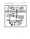
Use of the Continuous Mode
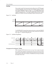
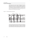
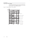
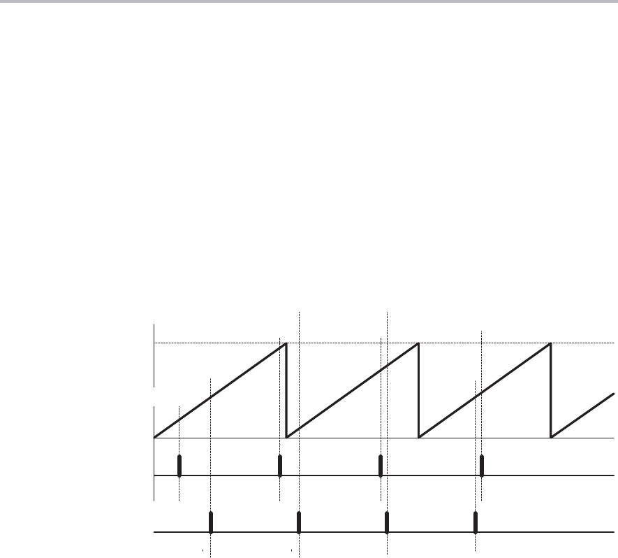
The continuous mode can be used to generate independent time intervals and
output frequencies. Each time an interval is completed, an interrupt is
generated. The next time interval is added to the TACCRx register in the
interrupt service routine. Figure 11−6 shows two separate time intervals t
0
and
t
1
being added to the capture/compare registers. In this usage, the time
interval is controlled by hardware, not software, without impact from interrupt
latency. Up to three independent time intervals or output frequencies can be
generated using all three capture/compare registers.
Figure 11−6. Continuous Mode Time Intervals
0FFFFh
TACCR0a
TACCR0b TACCR0c
TACCR0d
t
1
t
0
t
0
TACCR1a
TACCR1b TACCR1c
TACCR1d
t
1
t
1
t
0
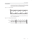
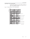
Time intervals can be produced with other modes as well, where TACCR0 is
used as the period register. Their handling is more complex since the sum of
the old TACCRx data and the new period can be higher than the TACCR0
value. When the previous TACCRx value plus t
x
is greater than the TACCR0
data, the TACCR0 value must be subtracted to obtain the correct time interval.