


ADC10 Registers
18-30
ADC10
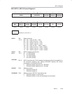
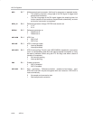
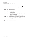
ADC10DTC0, Data Transfer Control Register 0
76543210
Reserved ADC10TB ADC10CT ADC10B1
ADC10
FETCH
r0 r0 r0 r0 rw−(0) rw−(0) rw−(0) rw−(0)
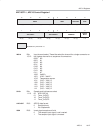
Reserved
Bits
7-4
Reserved. Always read as 0.
ADC10TB
Bit 3 ADC10 two-block mode.
0 One-block transfer mode
1 Two-block transfer mode
ADC10CT
Bit 2 ADC10 continuous transfer.
0 Data transfer stops when one block (one-block mode) or two blocks
(two-block mode) have completed.
1 Data is transferred continuously. DTC operation is stopped only if
ADC10CT cleared, or ADC10SA is written to.
ADC10B1
Bit 1 ADC10 block one. This bit indicates for two-block mode which block is filled
with ADC10 conversion results. ADC10B1 is valid only after ADC10IFG has
been set the first time during DTC operation. ADC10TB must also be set
0 Block 2 is filled
1 Block 1 is filled
ADC10
FETCH
Bit 0 This bit should normally be reset.