I
2
C Module Operation
15-10
USART Peripheral Interface, I
2
C Mode
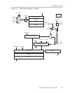
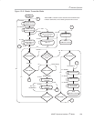
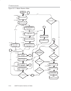
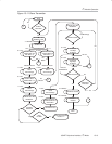
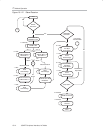
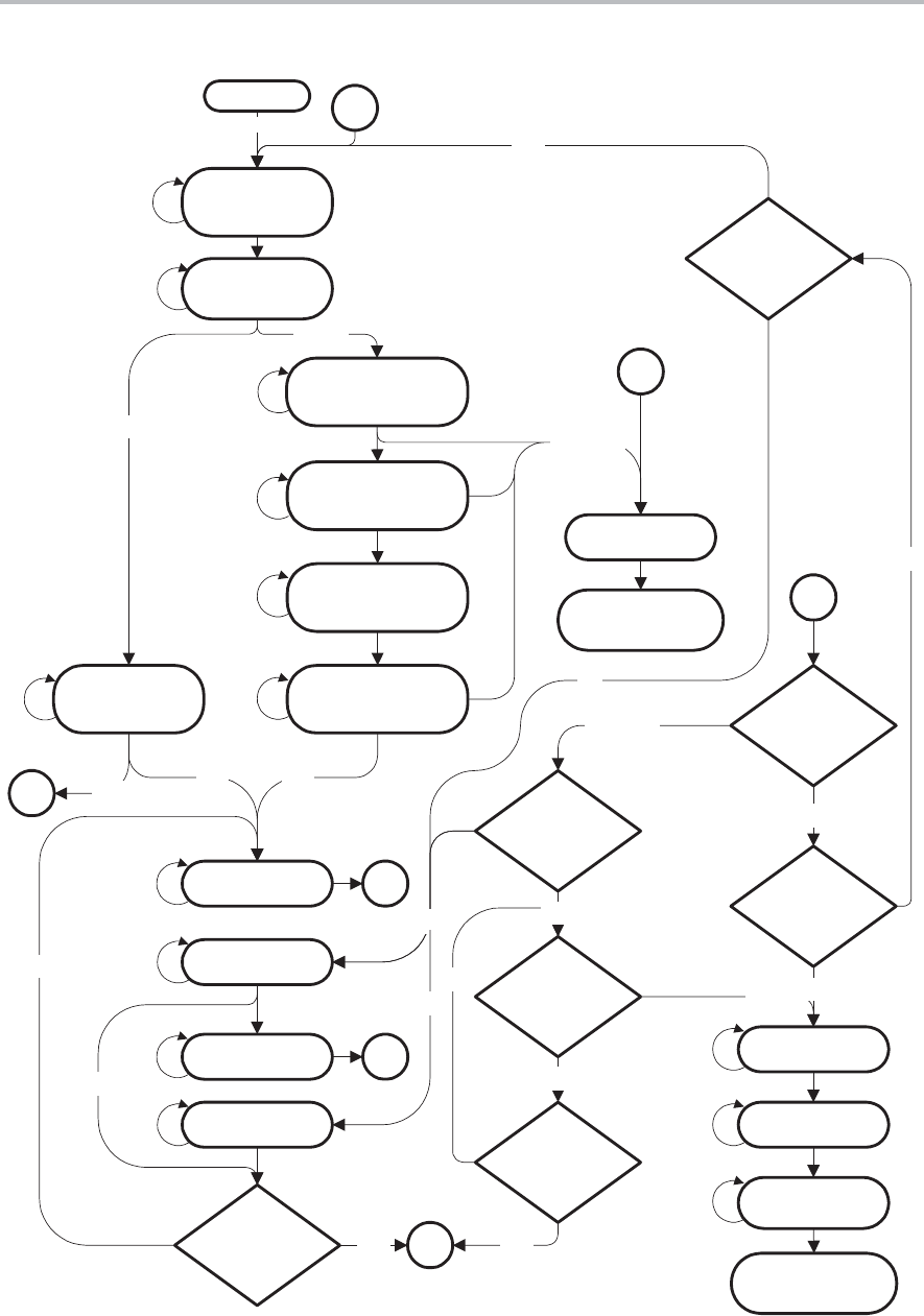
Figure 15−9. Master Receiver Mode
IDLE
Generate START
4 x I2CPSC
I2CBB Is Set
I2CSTT Is Cleared
8 x I2CPSC
Send Slave
Address Bits 6−0
with R/W = 1
8 x SCL
Send Slave Address
Bits 9−8 Extended
With R/W = 0
8 x SCL
STOP State?
STOP State?
I2CNDAT
Number Of Bytes
Received?
Repeat Mode?
Generate STOP
10 x I2CPSC
I2CBB Is Cleared
8 x I2CPSC
8 x I2CPSC
New START?
Receive Data
Low Byte
8 x SCL
New START?
2
NACKIFG Is Set
2
I2CWORD=0
I2CSTT=1
Generate Ack
For Low Byte
1 x SCL
Receive Data
High Byte
8 x SCL
Generate 2nd START
8 x SCL
4 x I2CPSC
Ack
New START?
3
I2CRM=1
I2CRM=0
No
No
Yes
Yes Yes
Yes, I2CSTP=1
No
Yes
No
IDLE
I2CBUSY Is Cleared
IDLE
I2CBUSY Is Cleared
Send Slave Address
Bits 9−8 Extended
With R/W = 1
Send Slave Address
Bits 7−0
8 x SCL
Ack
No Ack1
1
XA = 1
XA = 0
No Ack
I2CSTP, I2CMST
Are Cleared
3
3
No
Generate Ack
For High Byte
1 x SCL
Or
No


